
What is a TRIAC?
A TRIAC, short for Triode for Alternating Current, is a versatile electronic component that functions as a bidirectional switch for AC power. It enables current to flow in both directions when triggered, making it an ideal choice for controlling AC circuits in various applications. From dimmer switches to motor controls, TRIACs play a crucial role in managing power efficiently and reliably. This article will explore how TRIACs work, their advantages, and their common applications in modern electronic systems.

How Does a TRIAC Work?
Structure
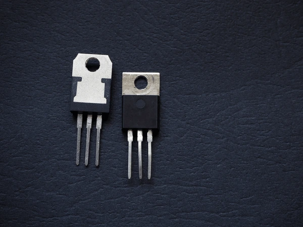
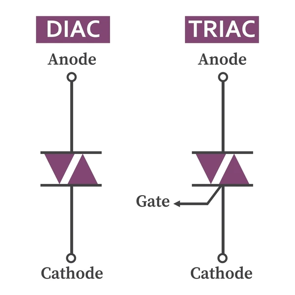
The device features three terminals: two main terminals for the AC power connection and a gate terminal for triggering. Inside, it consists of two silicon-controlled rectifiers (SCRs) connected in antiparallel, enabling bidirectional current flow.
Triggering
A small gate current, either positive or negative, triggers the device based on the main voltage’s polarity. This current only needs to be applied briefly, typically lasting just microseconds.
Conduction
After being triggered, the device conducts current until the flow drops below a specific threshold, usually at the AC cycle’s zero crossing. This characteristic makes it highly effective for phase-control applications, which are commonly used to regulate power.
Components and Structure of a TRIAC
Substrate and Doped Layers
This device typically uses a lightly-doped N-type semiconductor substrate as its foundation. The upper and lower surfaces feature P-type doped layers, complemented by heavily-doped N-type regions arranged in a complementary manner.
Electrodes
It includes two main electrodes, A1 and A2, positioned on the front and rear surfaces, respectively. A gate electrode is also included, which plays a key role in controlling conduction.
Structural Variations
The gate region may have a U-shaped design on the front surface, with its base positioned along one side of the structure. The primary front surface region is of the second conductivity type, surrounded by sections of the first conductivity type for enhanced performance.
Isolation and Passivation
To prevent voltage breakdowns, a mesa peripheral structure with lateral ring-shaped trenches filled with passivation materials like glass is incorporated. This design ensures high voltage durability by isolating potential breakdowns within the trenches, protecting the active regions.
Operation and Control
Conduction begins when a voltage is applied to the gate electrode relative to one of the main electrodes. By using Pulse Width Modulation (PWM) to adjust the gate signal, the conduction angle—and the energy delivered to the load—can be precisely controlled.
TRIAC vs. SCR: Key Differences
Construction
- SCR:
The Silicon-Controlled Rectifier is a unidirectional device, allowing current to flow in only one direction. It features three layers of semiconductor material, with a p-type layer positioned between two n-type layers. - Bidirectional Device:
A bidirectional device allows current to flow in both directions, unlike an SCR. Its structure is similar to an SCR but includes additional layers, enabling it to support bidirectional conduction.
Operation
- SCR:
An SCR conducts current during the positive half-cycle of an AC waveform. It requires a gate signal to trigger conduction and remains active until the current drops below a specific holding level. - Bidirectional Device:
This device conducts during both positive and negative half-cycles of an AC waveform. It triggers with a gate signal in either half-cycle, making it more efficient for AC power control.
Applications
- SCR:
SCRs are ideal for applications like motor control, lighting systems, power supplies, and phase control in dimming circuits. - Bidirectional Device:
Bidirectional devices are commonly used for AC power control in lighting dimmers, motor speed controllers, and power supplies. They excel in scenarios requiring bidirectional current control.
Control Mechanisms
- SCR:
Gate signals manage SCR conduction during specific AC cycle periods. Advanced techniques like pulse-width modulation (PWM) further optimize output power control. - Bidirectional Device:
These devices use gate signals in both AC half-cycles for precise power management. High-frequency sine wave control is also a popular method for added precision.
Advantages and Disadvantages
- SCR:
Advantages include high efficiency and reliability. However, the unidirectional nature requires additional components for full AC control. - Bidirectional Device:
Bidirectional conduction simplifies AC power control, offering flexibility. Yet, thermal management and control complexity can be potential challenges.
Common Issues and Failures in TRIACs
Diode-Mode Failure
Diode-mode failure occurs when the device allows only half-waves of mains voltage to pass, similar to a diode’s behavior. This can lead to motors receiving direct current, causing overheating and potential fire risks. Feedback circuits in control units can detect this issue early and interrupt the power supply to prevent damage.
Lessons from Structural Design Issues
Although unrelated to electronics, challenges in mechanical structural designs share parallels with system failures in circuit design. In column structures, issues like force-bearing performance and calculation analysis highlight the importance of thorough design. Similarly, rigorous analysis is critical in preventing failures in electronic systems.
Circuit Complexity and Safety
Designing circuits for load control involves significant complexity and cost, particularly with devices requiring double safety measures to meet regulatory standards. The challenge lies in simplifying these designs without compromising safety, making it a priority in modern system applications.
Applications of TRIAC
Motor Control
Electronic devices are commonly used to control motors, especially in applications with frequent start-stop cycles. They offer a reliable and cost-effective alternative to traditional relays, ensuring smoother operation and reduced wear.
Lighting Dimmers
Modern dimming circuits for LED lighting rely on efficient electronic components to adjust brightness by varying the firing angle. While effective, proper circuit design is essential to address challenges like current oscillations and maintain consistent performance.
AC Power Management
Devices that regulate AC power find applications in heating elements, lamps, and other load devices. Their ability to handle bidirectional current makes them a versatile choice for various power control needs.
Renewable Energy Systems
In renewable energy setups, these components play a key role in managing inverters and other control elements. They help optimize energy distribution and improve overall system efficiency.
Smart Home Integration
As smart home technology grows, power control components enhance the automation and functionality of devices, enabling efficient control of home appliances.
Latest Technical Innovations in TRIAC
Microgrid-Responsive Appliance Controllers
Innovative appliance controllers designed for microgrids ensure optimal electrical performance in commercial building energy management systems (EMS). These controllers incorporate an AC switch and an embedded Power Quality IoT sensor for monitoring electrical disturbances. Customizable alarms, compliant with IEEE-1547 standards, enhance system reliability. Operating autonomously or integrated with EMS, they support demand response strategies, preventing faults and blackouts in microgrid environments.
AC Motor Speed Control Applications
Efficient power regulation makes electronic switches ideal for speed control in AC motors. By modulating gate signals, they adjust voltage levels to manage motor speed effectively. Advanced techniques, such as over-zero crossing detection, delay gate pulses for precise and reliable speed adjustments in various applications.
PWM Control for Enhanced Performance
PWM (Pulse Width Modulation) is an advanced motor speed control method using power MOSFETs or IGBTs to switch high-frequency AC voltages. This approach generates time-varying voltages, offering superior control over motor speed and efficiency. Operating at frequencies between 10-20 kHz, PWM minimizes noise and electromagnetic interference (EMI), ensuring better performance and overall reliability.
To get detailed scientific explanations of TRIAC, try Patsnap Eureka.