
What is a Bridge Rectifier?
A bridge rectifier is a widely used electrical circuit that converts alternating current (AC) into direct current (DC), providing a crucial function in many electronic devices. Found in power supply units, it efficiently transforms AC voltage from mains supply into the DC voltage required by most modern electronics. The circuit’s unique diamond-shaped configuration of four diodes ensures full-wave rectification, utilizing both halves of the AC cycle for a smoother and more consistent output. This article will explore the structure, working mechanism, and applications of bridge rectifiers, highlighting their importance in power supply systems.
How Does a Bridge Rectifier Work?
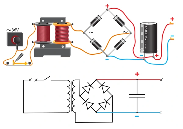
During the positive half of the AC signal, two diodes conduct, directing positive voltage to the load. Similarly, during the negative half, the other two diodes conduct, ensuring current flows in the same direction. This process results in a pulsating DC output with consistent polarity across both halves of the AC cycle.
Key Components of a Bridge Rectifier Circuit
Four Diodes: Four diodes form the core of the rectifier, arranged in a diamond shape. Two diodes conduct during the positive half-cycle of the AC input, while the other two conduct during the negative half, ensuring continuous rectification.
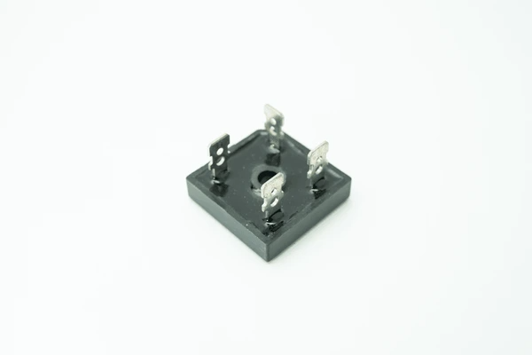
Lead Frame: Modern designs often integrate the diodes onto a lead frame for enhanced mechanical support and easier connection to input and output terminals.
Input and Output Terminals: The circuit features two AC input terminals and two DC output terminals. During each half-cycle of the AC input, pairs of diodes connect the corresponding input terminal to the appropriate output terminal, maintaining a consistent current direction.
Filter Capacitor: A capacitor is commonly added across the output terminals to smooth the rectified signal. This component minimizes AC ripple, providing a more stable DC output.
Control Unit (in Advanced Designs): Active rectifiers include a control unit to regulate power transistor switching. This addition improves efficiency, supports voltage regulation, and allows for reactive power management.
Advantages of Using a Bridge Rectifier
Bridge rectifiers offer high efficiency by eliminating the need for center-tapped transformers, minimizing energy losses, and supporting higher voltage levels. Their compact design and reduced component count lower costs while improving scalability. Modern configurations, especially with active switching devices, enable features like near-unity power factor, bidirectional power flow, and reactive power control, which are vital for applications like renewable energy and electric vehicles. They also reduce harmonic distortion, enhancing output quality and system stability.
The modular design of advanced rectifiers ensures scalability for large systems, while active devices improve reliability and lifespan by minimizing thermal and switching stress. These versatile rectifiers find use in diverse applications, from small electronics to industrial power systems, making them a cornerstone of modern electrical engineering solutions.
Applications of Bridge Rectifier
Power Supply Systems
Bridge rectifiers are essential in power supply systems, converting AC input into DC output for electronic devices. They are commonly used in both low- and high-voltage applications, ensuring efficient operation.
RFID Systems
In RFID systems, bridge rectifiers convert RF signals into DC voltage to power tag microchips. They are particularly effective in high-frequency applications, including HF and microwave RFID technologies.
Microwave Power Transmission
Bridge rectifiers are used in microwave power transmission to convert received microwave signals into DC power. These rectifiers can achieve efficiencies up to 80% at optimal input power levels, making them critical for high-efficiency systems.
Uninterruptible Power Supplies (UPS)
In UPS systems, bridge rectifiers charge batteries during mains power availability. This ensures a stable DC supply during power outages, supporting seamless operation.
Renewable Energy Systems
Renewable energy setups, including solar and wind systems, use bridge rectifiers to convert generated AC into DC for storage or further processing.
Telecommunications
Bridge rectifiers provide stable DC power in telecommunications equipment, ensuring reliable performance and maintaining signal quality in critical systems.
Medical Devices
Medical equipment, such as diagnostic and therapeutic devices, use bridge rectifiers to safely convert AC into DC, supporting efficient and safe operation.
Industrial Applications
Industrial systems like motor drives, control systems, and automation equipment rely on bridge rectifiers for consistent DC power, ensuring reliability in demanding environments.
Consumer Electronics
Bridge rectifiers are integral in consumer electronics, including televisions, computers, and audio equipment, where they convert household AC to DC for internal use.
Electric Vehicles (EVs)
In EV charging systems, bridge rectifiers convert grid AC into DC for battery charging, supporting efficient and reliable energy transfer in modern transportation solutions.
Application Cases
| Product/Project | Technical Outcomes | Application Scenarios |
|---|---|---|
| Autopilot Tesla | Using model quantization techniques, the inference speed is improved by 4 times, and the power consumption is reduced by about 2 times. | Resource-constrained edge devices, such as in-vehicle systems and other environments that require fast response. |
| Driving Circuit for Bridge Rectifier Chengdu Monolithic Power Systems Co. Ltd. | The driving circuit limits the driving signals for the low side switches to predetermined voltages, improving reliability and controllability. | Active bridge rectifier circuits in power conversion systems, electrical equipment, and emergency protection circuits. |
| Bridge Rectifier Circuit Component SIRECTIFIER ELECTRONIC COMPANY LIMITED | Simplified manufacturing process, improved heat dissipation, reduced costs, and enhanced product consistency and reliability. | Single-phase and three-phase bridge rectifier circuits in power conversion systems and electrical apparatus. |
| Synchronous Bridge Rectifier Champion Microelectronic Corp. | Improved efficiency by addressing issues related to conventional bridge rectifiers. | Bridge rectifier applications where efficiency is a concern. |
| Power Efficient Bridge Rectifier Implemented with Switches Lite-On Electronics (Guangzhou) Co., Ltd. | Reduced complexity, power consumption, voltage drop, and power loss compared to diode-based bridge rectifiers. | Bridge rectifier applications where power efficiency and reliability are important. |
Latest Technical Innovations in Bridge Rectifier
Improved Rectifier Circuits for Energy Harvesting
A novel H-Bridge rectifier circuit enhances energy harvesting from piezoelectric systems. It minimizes power loss, especially at high frequencies and low amplitudes, by utilizing a series-connected gate diode configuration with NMOS FETs. This design also improves breakdown voltage, ensuring reliable operation in demanding applications.
Active Rectifier Circuit Innovations
An advanced active rectifier circuit integrates a rectifier and control unit. By employing signal comparators, the control unit manages switching operations, significantly boosting power efficiency and offering greater flexibility in power management.
Power-Efficient Switching Solutions
A rectifier circuit optimized with advanced switching technologies reduces power dissipation. Low-impedance switching circuits enhance performance, making the design ideal for modern energy-efficient systems.
High-Frequency Integration and Applications
A cutting-edge 2.4 GHz SOI-CMOS rectifier IC supports sub-W class rectification. It incorporates NMOS FETs in series for higher breakdown voltages and a low-pass filter to counter efficiency loss from junction capacitance. This compact design achieves 44.2% rectification efficiency at 27 dBm input power, making it suitable for integrated circuits and high-frequency use.
High Voltage and High Power Solutions
High-voltage rectifiers are now designed with reduced parasitic inductance and surge current. Compact yet powerful, they deliver efficient rectification for electric vehicles and telecommunication systems, ensuring durability and performance.
Innovations in Three-Phase Rectifiers
Recent advancements in three-phase rectifiers focus on improving power factor correction. A Boost secondary circuit with hysteresis loop control, combined with input filters, enhances the input power factor from 0.950 to 0.994. This efficient design is cost-effective, simple to control, and ensures superior power management.
To get detailed scientific explanations of Bridge Rectifier, try Patsnap Eureka.