Supercharge Your Innovation With Domain-Expert AI Agents!

Backlight module and plate of guiding light

A light guide plate and backlight module technology, applied in optics, nonlinear optics, instruments, etc., can solve the problems of high cost and backlight module thickness, and achieve the effect of reducing thickness

Inactive Publication Date: 2008-10-15
HONG FU JIN PRECISION IND (SHENZHEN) CO LTD +1
View PDF5 Cites 1 Cited by
  • Summary
  • Abstract
  • Description
  • Claims
  • Application Information

AI Technical Summary

Problems solved by technology

[0004] Because the backlight module 8 is formed by stacking two diffusion plates 83, 86, two light concentrating plates 84, 85 and a light guide plate 82, the backlight module is thicker and heavier, and its cost is also higher.

Method used


Image

  • Backlight module and plate of guiding light
  • Backlight module and plate of guiding light
  • Backlight module and plate of guiding light

Examples


Embodiment Construction

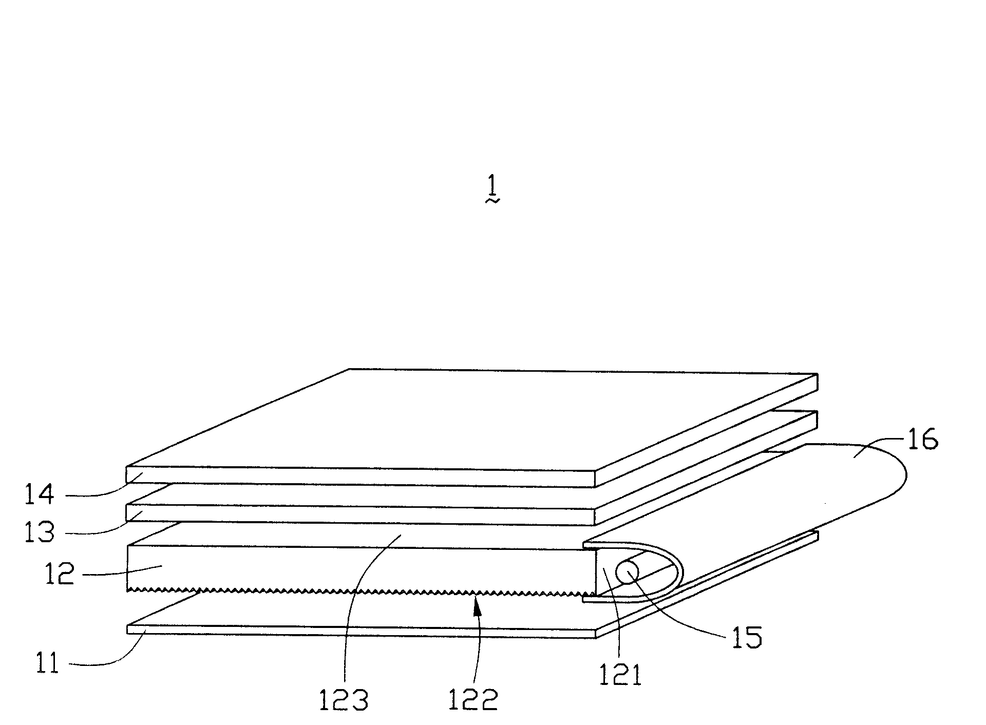
[0014] refer to figure 2 , is a perspective view of the first embodiment of the backlight module of the present invention. The backlight module 1 includes a reflection plate 11 , a light guide plate 12 , a light collecting plate 13 , a diffusion plate 14 , a light source 15 and a light source cover 16 . The light guide plate 12 includes a light incident surface 121 , a bottom surface 122 and a light exit surface 123 . The bottom surface 122 of the light guide plate 12 is provided with a V-shaped groove structure integrally formed with the light guide plate 11 , and the light emitting surface 123 of the light guide plate 12 is a rough surface integrally formed with the light guide plate. The light beam emitted by the lamp tube 15 enters from the light incident surface 121 of the light guide plate 12, is reflected by the reflector 11 and condensed by the V-shaped groove structure of the bottom surface 122, and then emerges from the light exit surface 123, because the light exi...


PUM


Abstract

The present invention discloses a backlight module, including a light source, a light-conducting plate, a light-reflecting plate, a light-collecting plate and a diffusion plate, in which said light-conducting plate has a light-entering surface, opposite undersurface and a light-exiting surface. Said light source is placed opposite to said light-entering surface, and said under surface is equipped with V-shaped groove structure, and said light-exiting surface is rough surface.

Description

【Technical field】 [0001] The invention relates to a backlight module and a light guide plate thereof. 【Background technique】 [0002] The liquid crystal display device is a kind of non-self-luminous display device, and its display is mainly realized by controlling the passage or non-passage of the light beam emitted by the external light source, so a corresponding backlight or front light module is required, and the backlight or front light module can The light beam emitted by the external light source is guided to the display panel to realize the display function. [0003] see figure 1 , is a prior art backlight module. The backlight module 8 includes a reflector 81 , a light guide plate 82 , a first diffuser 83 , a first light collector 84 , a second light collector 85 , a second diffuser 86 , a light tube 87 and a light source cover 88 . The light guide plate 82 includes a light incident surface 821 , a bottom surface 822 and a light output surface 823 . The reflectiv...

Claims


Application Information

Patent Timeline
Patent Type & Authority Patents(China)
IPC IPC(8): G02F1/1335G02F1/13357
Inventor 郑文峰陈杰良
Owner HONG FU JIN PRECISION IND (SHENZHEN) CO LTD
Features
  • R&D
  • Intellectual Property
  • Life Sciences
  • Materials
  • Tech Scout
  • Unparalleled Data Quality
  • Higher Quality Content
  • 60% Fewer Hallucinations
Learn More