Supercharge Your Innovation With Domain-Expert AI Agents!

Read-only memory cell capable of electrical erasure and programming, and its programmed method

A technology of read-only storage and electrification, which is applied in the direction of electrical components, circuits, electric solid-state devices, etc., and can solve problems such as the inability to reach the threshold voltage level, no structure, and inconvenience

Active Publication Date: 2009-06-24
MACRONIX INT CO LTD
View PDF3 Cites 0 Cited by
  • Summary
  • Abstract
  • Description
  • Claims
  • Application Information

AI Technical Summary

Problems solved by technology

Depend on Figure 2B It can be seen that although more electrons are stored on both sides of the charge trapping layer, its effective threshold voltage is still affected by whether the voltage is applied to the adjacent source / drain regions.
In other words, the bit stored on the right side of the charge trapping layer is affected by the source / drain region on the right, so the effective threshold voltage will still drop, so that it cannot reach the threshold value similar to the bit stored on the left side of the charge trapping layer voltage level
[0008] It can be seen that the above-mentioned existing electrically erasable and programmable read-only memory unit obviously still has inconvenience and defects in structure, programming method and use, and needs to be further improved urgently.
In order to solve the problems of electrically erasable and programmable read-only memory cells and their programming methods, relevant manufacturers have tried their best to find solutions, but no suitable design has been developed for a long time. However, general products do not have an appropriate structure to solve the above problems. This is obviously a problem that relevant industry players are eager to solve.

Method used


Image

  • Read-only memory cell capable of electrical erasure and programming, and its programmed method
  • Read-only memory cell capable of electrical erasure and programming, and its programmed method
  • Read-only memory cell capable of electrical erasure and programming, and its programmed method

Examples


Embodiment Construction

[0041] In order to further explain the technical means and effects of the present invention to achieve the intended purpose of the invention, in conjunction with the accompanying drawings and preferred embodiments, the electrically erasable and programmable read-only memory unit and Its programming method, its specific implementation, structure, method, steps, features and effects, are described in detail below.

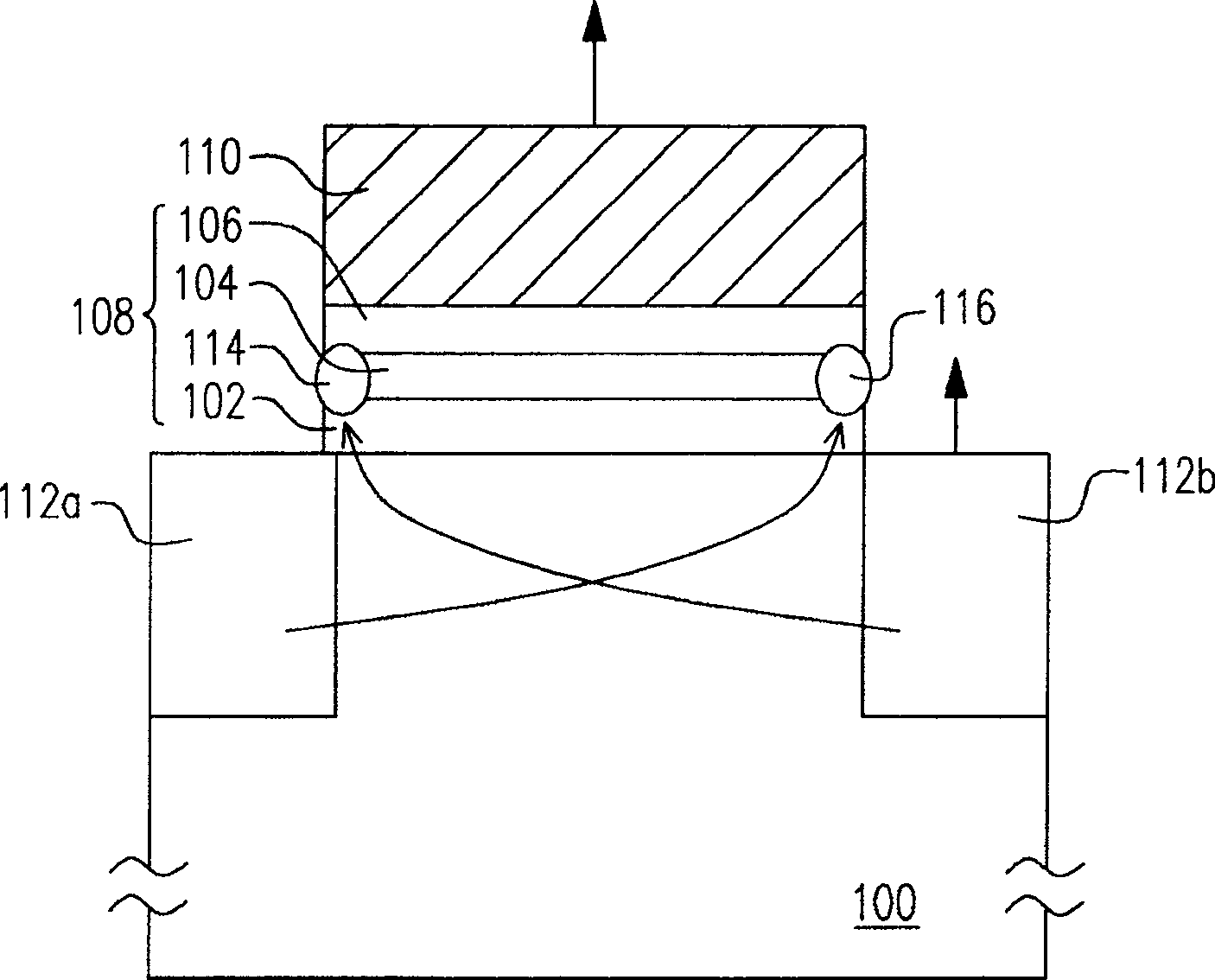
[0042] see image 3 Shown is a schematic cross-sectional view of an electrically erasable and programmable read-only memory unit according to a preferred embodiment of the present invention.

[0043] Such as image 3 As shown, the electrically erasable and programmable read-only memory cell of the present invention is composed of a substrate 300, a stack layer 302, a gate conductive layer 304, source / drain regions 306a, 306b, pocket implant doped impurity regions 308a and 308b.

[0044] Wherein, the substrate 300 is, for example, a silicon substrate, which may be ...


PUM


Abstract

The invention relates to an electrically erasable and programmable read-only memory unit and a programming method thereof. The electrically erasable and programmable read-only memory unit is composed of a stacked layer and a gate conductive layer. , composed of a first source / drain region, a second source / drain region, a first pocket implanted doped region and a second pocket implanted doped region. Wherein, the stacked layers are arranged on the substrate. In addition, the gate conductive layer is configured on the stacked layer. In addition, the first source / drain region and the second source / drain region are respectively arranged in the substrate on both sides of the gate conductive layer. In addition, the first pocket implant doped region is disposed in the substrate below the stacked layer and is adjacent to the first source / drain region. In addition, the second pocket implanted doped region is disposed in the substrate below the stacked layer and adjacent to the second source / drain region, and the doping concentration of the first pocket implanted doped region is different from that of the second pocket The doping concentration of the implanted doped region.

Description

technical field [0001] The present invention relates to a memory element and its programming method, in particular to an electrically erasable and programmable read-only memory cell (Electrically Erasable Programmable Read Only Memory Cell, EEPROM Cell) and its programming method. Background technique [0002] Electrically erasable and programmable read-only memory has the advantages of multiple data storage, reading and fast erasing, and the stored data will not disappear after power off, so It has become a non-volatile memory element widely used in personal computers and electronic equipment. [0003] Silicon nitride read-only memory is a commonly used electrically erasable and programmable read-only memory. Its memory cell structure is as follows: figure 1 shown. see figure 1 As shown, the silicon nitride read-only memory cell is composed of a silicon oxide tunneling dielectric layer 102 / silicon nitride charge trapping layer 104 / silicon oxide blocking dielectric layer ...

Claims


Application Information

Patent Timeline
Patent Type & Authority Patents(China)
IPC IPC(8): H01L27/115H01L21/8247H10B43/30
Inventor 吴昭谊李明修
Owner MACRONIX INT CO LTD
Features
  • R&D
  • Intellectual Property
  • Life Sciences
  • Materials
  • Tech Scout
  • Unparalleled Data Quality
  • Higher Quality Content
  • 60% Fewer Hallucinations
Learn More