Image forming device
An image and image bearing technology, which is applied in the direction of corona discharge devices, electric recording technology using charge patterns, equipment for electric recording technology using charge patterns, etc., can solve the problem of reducing the printing speed of image forming devices, the error of discharge current value, Discharge current changes and other issues
- Summary
- Abstract
- Description
- Claims
- Application Information
AI Technical Summary
Problems solved by technology
Method used
Image

Examples
no. 1 example
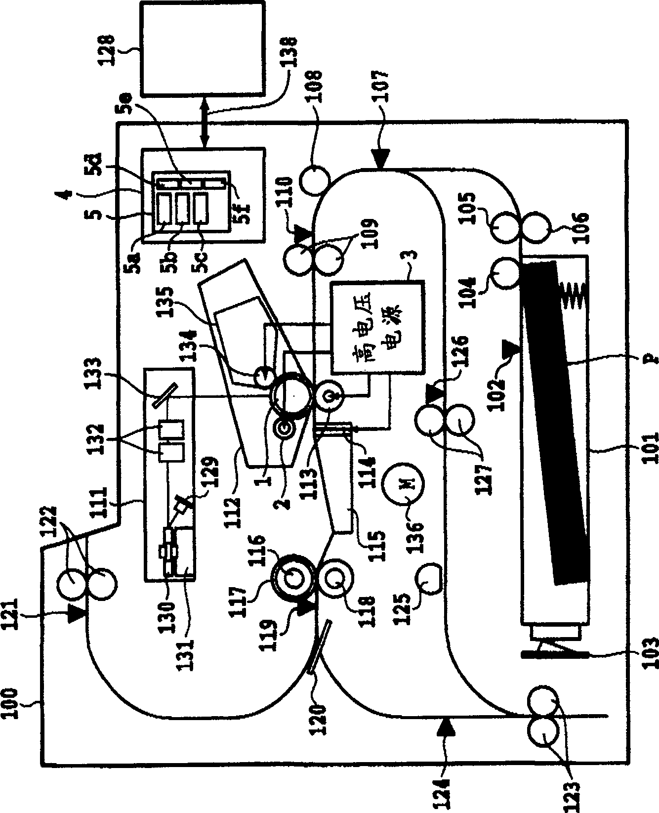
[0052] The first embodiment of the present invention will be described below according to the accompanying drawings, figure 2 It is a configuration diagram of the laser printer 100 of the present embodiment and the second to seventh embodiments.
[0053] The laser printer 100 includes a table 101 for storing recording paper P, an in-table recording paper sensor 102 for detecting the presence or absence of recording paper P in the table 101, a paper size detection sensor 103 for detecting the size of the recording paper P in the table 101, and The pickup roller 104 that pulls out the recording paper P from the table 101, the table feed roller 105 that conveys the recording paper P pulled out by the pickup roller 104, and the table feed roller 105 that form a pair to prevent obstruction of conveying the stacked recording paper P Roller 106.
[0054] Downstream of the table top paper feed roller 105, a paper feed sensor 107 is arranged to detect the conveyance state of the pape...
no. 2 example
[0116] Next, a second embodiment of the present invention will be described. In the first embodiment, the detection of the nip current is performed by detecting the peak value of the differential value of the charging AC voltage. In the second embodiment, the detection of the nip current is performed according to the phase shift of the AC voltage in the predetermined phase interval.
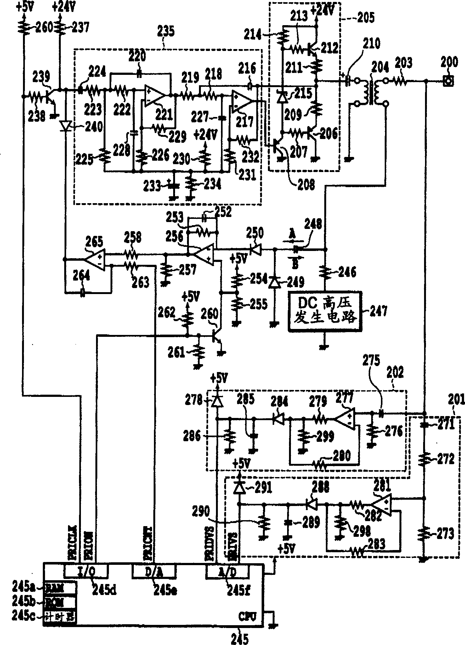
[0117] Figure 11 It is a circuit diagram of the charging high-voltage output circuit of the image forming apparatus of the second embodiment, and its basic configuration is the same as that of the circuit of the first embodiment.
[0118] The difference with the first embodiment is that the voltage detection circuit 202 as the differential voltage detection circuit of the first embodiment is not provided, and the zero-crossing detection circuit 1009 for detecting the zero-crossing point of the positive and negative switching of the AC waveform and detecting the charging AC are provided. A circ...
no. 3 example
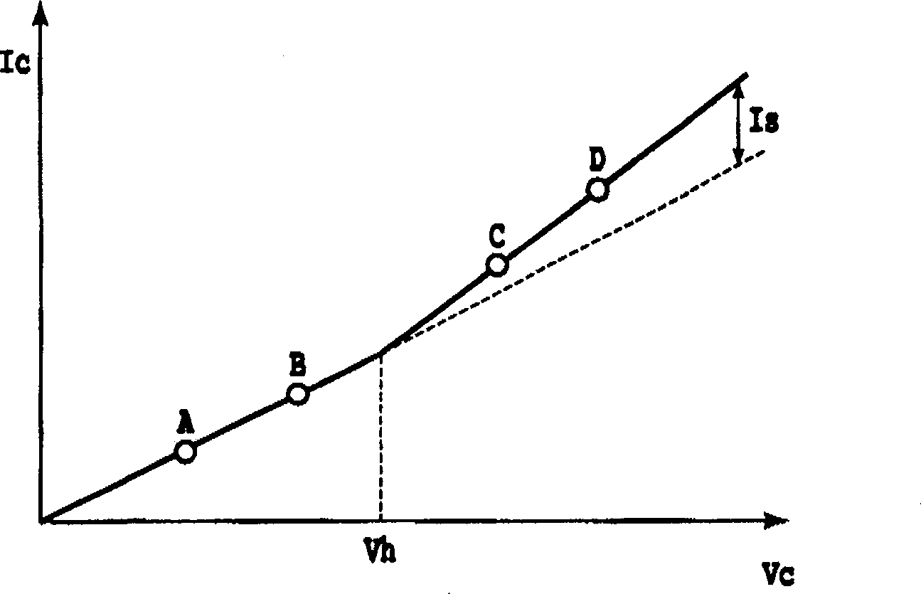
[0144] Figure 16A The relationship between the peak value of the charging AC voltage and the peak value of the differential value of the charging AC voltage (horizontal axis) and the charging current Ic (vertical axis) of the third embodiment is shown. For the charging high voltage control of the third embodiment, refer to Figure 16A Be explained. In the present embodiment, the charging AC voltage is applied to the charging roller so that the charging current Ic becomes a predetermined value Iac1, and then the following processing is performed.
[0145] Initially, the peak value Vac1 of the charging AC voltage corresponding to the intersection point a of the characteristic curve LINE A (the peak value of the charging AC voltage) and the straight line representing the charging current Iac1 is detected by the voltage detection circuit 201, and the peak value Vac1 of the charging AC voltage corresponding to the characteristic curve LINE B is detected by the voltage detection ci...
PUM
 Abstract
Description
Claims
Application Information
 - R&D
- Intellectual Property
- Life Sciences
- Materials
- Tech Scout
- Unparalleled Data Quality
- Higher Quality Content
- 60% Fewer Hallucinations
Browse by: Latest US Patents, China's latest patents, Technical Efficacy Thesaurus, Application Domain, Technology Topic, Popular Technical Reports.
© 2025 PatSnap. All rights reserved.Legal|Privacy policy|Modern Slavery Act Transparency Statement|Sitemap|About US| Contact US: help@patsnap.com