Check patentability & draft patents in minutes with Patsnap Eureka AI!

Toner compensation vessel and imaging device thereof

An imaging device and toner technology, which is applied in the direction of instruments, equipment for electric recording technology using charge patterns, optics, etc., can solve the problems of rising device cost, complexity, and the inability to replace the device immediately

Inactive Publication Date: 2009-07-08
CANON KK
View PDF3 Cites 0 Cited by
  • Summary
  • Abstract
  • Description
  • Claims
  • Application Information

AI Technical Summary

Problems solved by technology

[0050] (4) The correct bottle is prepared, but the device cannot be replaced immediately during the operation
[0057] (5) Although the image formation is restarted, but the toner bottle is not replaced, it immediately shows that there is no toner
[0058] In this way, when only the opening and closing detection of the front cover is used as a judgment signal for bottle replacement, when the user performs an abnormal operation, although the toner bottle is not replaced, the display of the operation part returns to the normal display or repeats. multiple recovery actions
[0059] In order to solve this problem, it is conceivable to install additional detection means that can detect the presence or absence of the toner bottle, but it will increase the cost and complicate the device, so it is not the best solution

Method used


Image

  • Toner compensation vessel and imaging device thereof
  • Toner compensation vessel and imaging device thereof
  • Toner compensation vessel and imaging device thereof

Examples


Embodiment 1

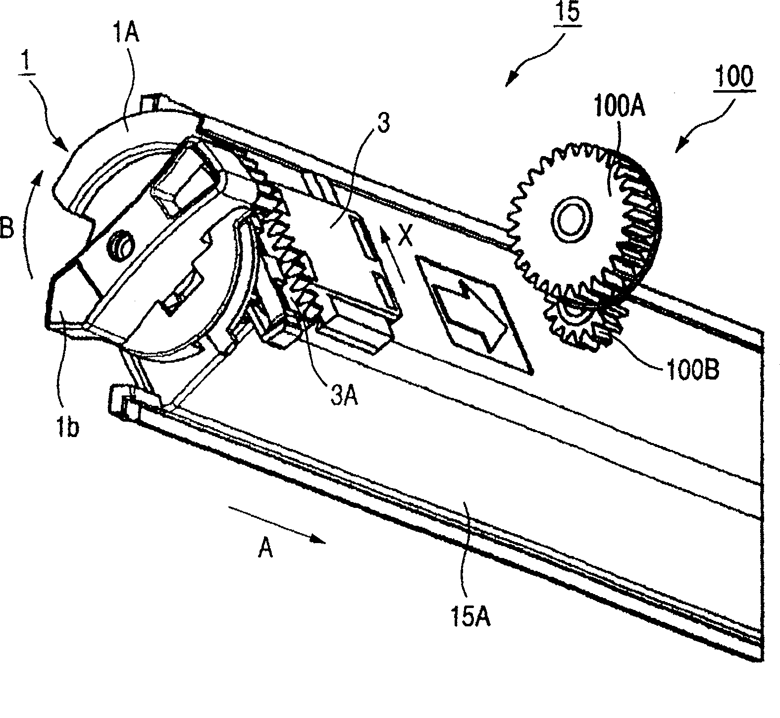
[0075] use Figure 1A and 1B The first embodiment of the present invention will be described. The configuration of the toner bottle is basically the same as that described in the above conventional example except for the configuration of the detected portion. Therefore, parts having the same functions as those in the conventional example are denoted by the same reference numerals, and detailed descriptions thereof are omitted. 1A and 1B are schematic diagrams of parts of imaging devices that can use the present invention.


PUM


Abstract

The present invention discloses a toner supply container and an image forming apparatus. The presence or absence of the toner bottle cannot be detected by the existing mechanism for detecting the position of the knob of the toner bottle. Therefore, in the toner supply container and the image forming apparatus of the present invention, by disposing the optical sensor on the inner surface of the replacement door facing the knob of the toner bottle, the presence or absence of the toner bottle can be detected and the position of the knob can be detected That is, the detection of the opening and closing of the shutter of the toner bottle.

Description

technical field [0001] The present invention relates to a toner supply container detachably mounted on an image forming apparatus such as an electrophotographic or electrostatic recording system, such as a copier, a printer, or a facsimile, and an image forming apparatus that supplies toner from the toner supply container. Background technique [0002] Conventional imaging devices capable of multicolor recording are as follows. [0003] use image 3 Be explained. image 3 It is a perspective view of the above-mentioned rotating body. [0004] A plurality of developing mechanisms (hereinafter referred to as the developing device 52) and a plurality of containers (hereinafter referred to as the toner bottle 15) corresponding to them for storing the developer (hereinafter referred to as the toner) are arranged in a circular shape in a cylindrical shape. The so-called rotary developing device inside the rotating body 51. [0005] Reference numeral 51 is the entire rotating bod...

Claims


Application Information

Patent Timeline
Patent Type & Authority Patents(China)
IPC IPC(8): G03G15/08G03G21/00G03G15/01
CPCG03G15/0886G03G15/0868G03G15/0839G03G2215/0692G03G15/0877
Inventor 堀越淳田村昌重
Owner CANON KK
Features
  • R&D
  • Intellectual Property
  • Life Sciences
  • Materials
  • Tech Scout
  • Unparalleled Data Quality
  • Higher Quality Content
  • 60% Fewer Hallucinations
Learn More