Check patentability & draft patents in minutes with Patsnap Eureka AI!

Rotor of hydraulic pump

A hydraulic pump and rotor technology, applied in the field of hydraulic pumps, can solve problems such as flow pulsation, and achieve the effects of reducing noise, simple structure, and reducing noise

Active Publication Date: 2009-10-28
叶会昌
View PDF8 Cites 0 Cited by
  • Summary
  • Abstract
  • Description
  • Claims
  • Application Information

AI Technical Summary

Problems solved by technology

[0006] 2. The influence of the compressibility of the working medium, for example, the actual pressure in the working volume of the gear pump changes with the rotation of related components and the flow channel impedance, which will also cause additional flow pulsation

Method used


Image

  • Rotor of hydraulic pump
  • Rotor of hydraulic pump
  • Rotor of hydraulic pump

Examples


Embodiment Construction

[0023] The following are specific embodiments of the present invention and in conjunction with the accompanying drawings, the technical solutions of the present invention are further described, but the present invention is not limited to these embodiments.

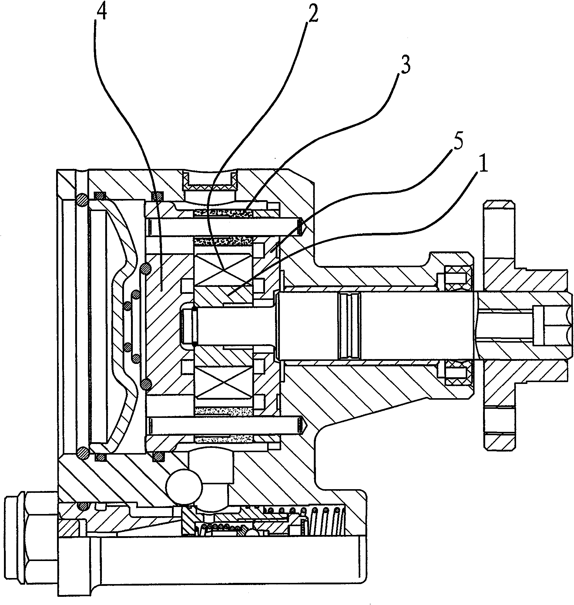
[0024] Such as figure 1 As shown, the rotor of the hydraulic pump is the rotor on the vane pump, and the rotor, the stator 3, the upper oil distribution plate 4, and the lower oil distribution plate 5 form a flow-through assembly.

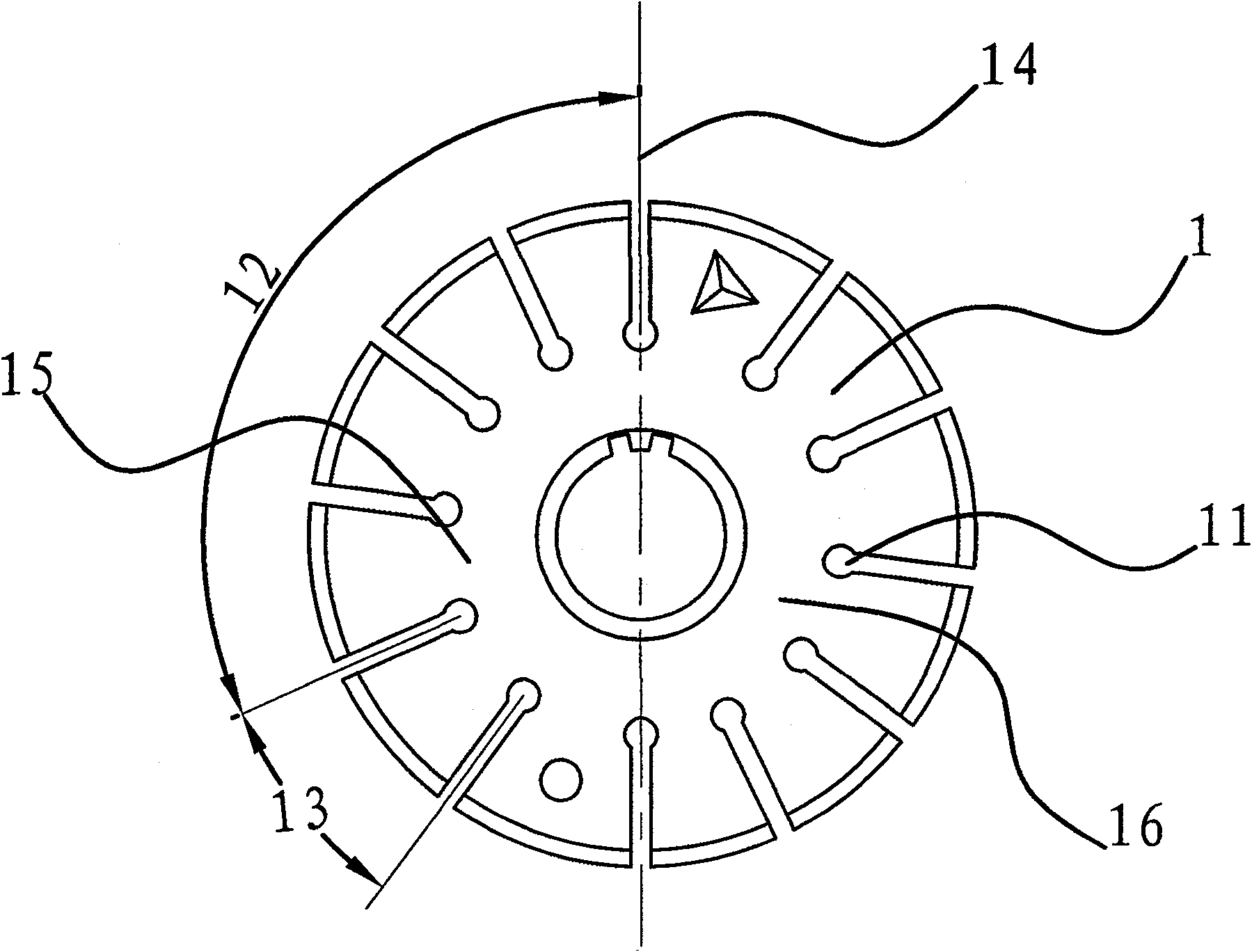
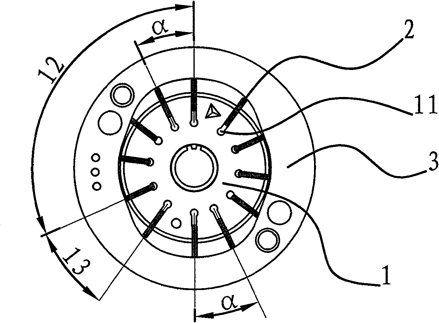
[0025] The rotor consists of a cylindrical rotor body 1 and flat blades 2 . The above-mentioned rotor body 1 is provided with 12 grooves 11 in the radial direction, and the 12 blades 2 are movably inserted into the grooves 11 . During the rotation of the rotor body 1, the vane 2 will protrude radially outward due to the inertia, and press against the stator, between the stator 3, the two vanes 2, the upper oil distribution plate 4 and the lower oil distribution plate 5 A working chamber is fo...


PUM


Abstract

The invention provides a hydraulic pump rotor, which belongs to the technical field of hydraulic pumps. It solves the problem that the existing hydraulic pump rotor makes the hydraulic pump generate noise due to flow and pressure pulsation. The rotor of the hydraulic pump includes a cylindrical rotor body and several flat blades, these blades are movably inserted on the rotor body along the radial direction of the rotor body, and the blades are distributed on the rotor body in an unequal manner . The rotor of the hydraulic pump can effectively reduce the flow and pressure pulsation of the hydraulic pump so as to reduce noise and have a simple structure.

Description

technical field [0001] The invention belongs to the technical field of hydraulic pumps and relates to a hydraulic pump rotor. Background technique [0002] With the popularization of automobiles, people have higher and higher requirements for the performance and driving comfort of automobiles, and the reliability, portability and sensitivity of automobile steering are one of them. Therefore, in the steering system of automobiles A hydraulic power steering system is used. [0003] In the prior art, a hydraulic pump includes a rotor, a stator, vanes and an oil distribution plate, wherein the vanes are movably connected to the rotor in an equal division and can freely slide radially, and the rotor is arranged in the stator. During the rotation of the rotor, due to the action of inertial force, the blades always lean on the inner curved surface of the stator, forming a working cavity between the adjacent blades and the left and right oil distribution plates, because the inner s...

Claims


Application Information

Patent Timeline
Patent Type & Authority Patents(China)
IPC IPC(8): F04C2/344
Inventor 叶会昌
Owner 叶会昌
Features
  • R&D
  • Intellectual Property
  • Life Sciences
  • Materials
  • Tech Scout
  • Unparalleled Data Quality
  • Higher Quality Content
  • 60% Fewer Hallucinations
Learn More