Check patentability & draft patents in minutes with Patsnap Eureka AI!

Novel high efficiency wave guide

A technology for microwave heating equipment and waveguides, applied in the field of waveguides, achieves the effects of simple and convenient installation process, improved efficiency, and reduced transmission energy consumption

Inactive Publication Date: 2009-11-25
李金财
View PDF6 Cites 1 Cited by
  • Summary
  • Abstract
  • Description
  • Claims
  • Application Information

AI Technical Summary

Problems solved by technology

[0004] The purpose of the present invention is to overcome the above-mentioned defects in the prior art, solve the problems of improving the transmission efficiency of the waveguide and the installation of the magnetron and the cooling fan, and provide a waveguide for microwave heating equipment, which has high efficiency, combined Features of easy installation

Method used


Image

  • Novel high efficiency wave guide
  • Novel high efficiency wave guide
  • Novel high efficiency wave guide

Examples


Embodiment 1

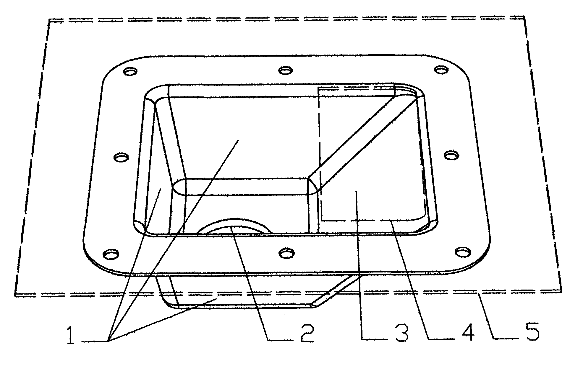
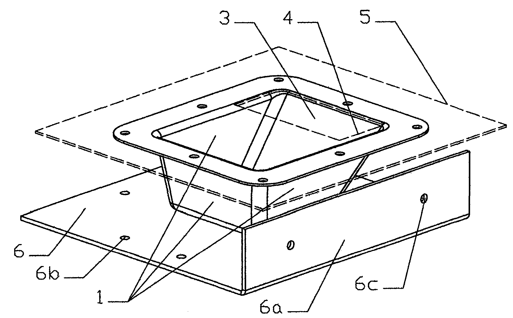
[0015] Embodiment 1. The structure of the waveguide of the present embodiment microwave heating equipment can be from figure 2 and image 3 As can be seen in the figure, it has four oblique sides, which are three secondary reflection surfaces 1 and one third reflection surface 3 respectively, a microwave input port 2 is arranged on the bottom plane, the waveguide 7 and the mounting plate 5 on the microwave heating equipment After being fixed, a launch port 4 is formed on the three-time reflective surface 3 .

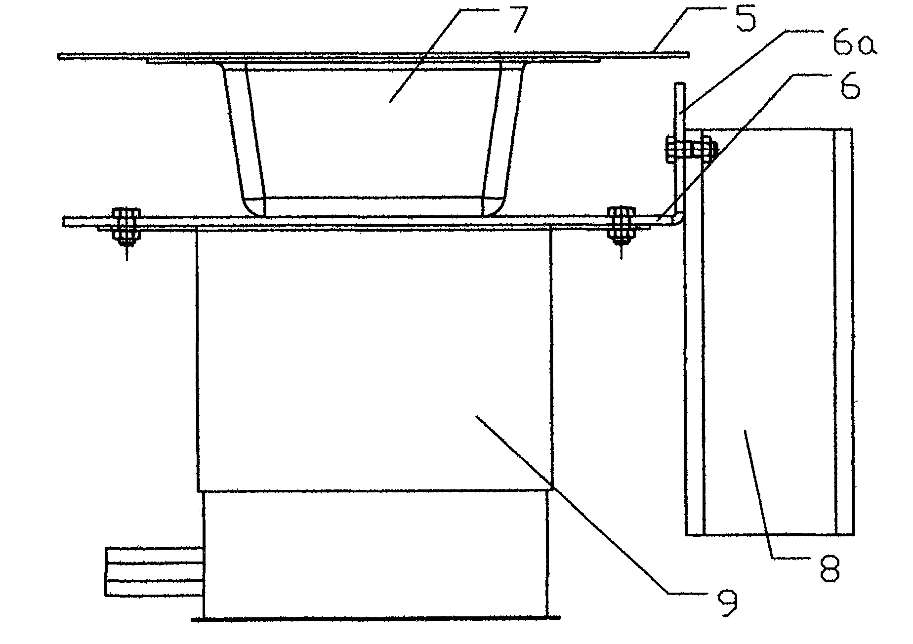
[0016] Such as figure 2 As shown, a base plate 6 with a folded edge 6a is welded on the bottom plane of the waveguide 7, and four sets of 8 through holes are averagely opened on the base plate 6 around the microwave input port 2 of the waveguide 7 to form two sets of mutually perpendicular arrangements. The magnetron installation hole 6b; the folded edge 6a is bent in a direction close to the waveguide 7, and two fan installation holes 6c are opened on the folded edg...

Embodiment 2

[0018] Embodiment 2. The structure of the waveguide of the microwave heating equipment of this embodiment can be obtained from Figure 4 and Figure 5 It can be seen from the figure that it is different from Embodiment 1 in that it reduces the slope of one of the secondary reflection surfaces 1 adjacent to the three reflection surface 3 on the waveguide 7 until it is equal to the slope of the three reflection surface 3 , and extend the top edge of the secondary reflection surface 1 outwards, so that the secondary reflection surface 1 becomes the second third reflection surface, and open two openings on the mounting plate 5 fixed with the waveguide 7 on the microwave heating equipment, They correspond to the positions of the two three-time reflecting surfaces 3 , and when the waveguide 7 is installed, these two ports and the waveguide form two emission ports 4 .

[0019] In this way, the secondary reflection surface 1 on the waveguide 7 is reduced to two, and the launch port 4...


PUM


Abstract

The invention can be installed with a magnetron and a radiation fan and can be formed with two transmission port to transmit microwave. The method comprises: binding a base plate with a folded edge on the bottom side of the waveguide tube; around the microwave entrance of the waveguide tube there are eight through hole in four groups used for mounting magnetron and mounting fan on the through holes on the folded edge; reducing the grade of slop of a secondary reflection face adjacent to the triple reflection face on the magnetron; extending out the edge of face top to make the face to become a second triple reflection; making two openings corresponding to said two triple reflection face on the mounting board where the magnetron is secured; after the magnetron is installed, two transmission ports are formed so as the microwave can be rapidly transmitted out.

Description

1. Technical field [0001] The invention relates to a waveguide, in particular to a waveguide for microwave heating equipment, which can be directly installed with a magnetron and a cooling fan, and can form two launching ports to transmit microwaves. 2. Background technology [0002] In the microwave heating equipment, since the magnetron emits microwaves at one point, the microwaves are too concentrated to be unfavorable for heating. Therefore, a waveguide is used between the magnetron and the microwave heater to diverge the microwaves and then send them into the microwave heater. The waveguide uses the reflective surface to diverge microwaves, while the traditional reflective waveguide has three secondary reflective surfaces 1, a third reflective surface 3, a microwave input port 2 and a launch port 4 after installation, such as figure 1 As shown, there are many secondary reflection surfaces, and each reflection will generate a certain amount of energy consumption, which r...

Claims


Application Information

Patent Timeline
Patent Type & Authority Patents(China)
IPC IPC(8): H05B6/64H05B6/72F24C7/02H01P5/12H01P7/00
Inventor 李金财
Owner 李金财
Features
  • R&D
  • Intellectual Property
  • Life Sciences
  • Materials
  • Tech Scout
  • Unparalleled Data Quality
  • Higher Quality Content
  • 60% Fewer Hallucinations
Learn More