Unlock instant, AI-driven research and patent intelligence for your innovation.
Imaging lens group
What is Al technical title?
Al technical title is built by PatSnap Al team. It summarizes the technical point description of the patent document.
An imaging lens and lens technology, applied in optics, instruments, optical components, etc., can solve the problems of high sensitivity of imaging lens group and increase of stray light, and achieve the effect of improving sensitivity, reducing possibility and good imaging quality.
Active Publication Date: 2009-12-23
LARGAN PRECISION
View PDF4 Cites 0 Cited by
Summary
Abstract
Description
Claims
Application Information
AI Technical Summary
This helps you quickly interpret patents by identifying the three key elements:
Problems solved by technology
Method used
Benefits of technology
Problems solved by technology
In order to correct aberrations, the form of a front aperture is generally used, but the configuration of the front aperture will increase the stray light, and the sensitivity of the imaging lens group is also greater
Method used
Image
Click on the blue label to locate the original text in one second.
Reading with bidirectional positioning of images and text.
Examples
Embodiment 1
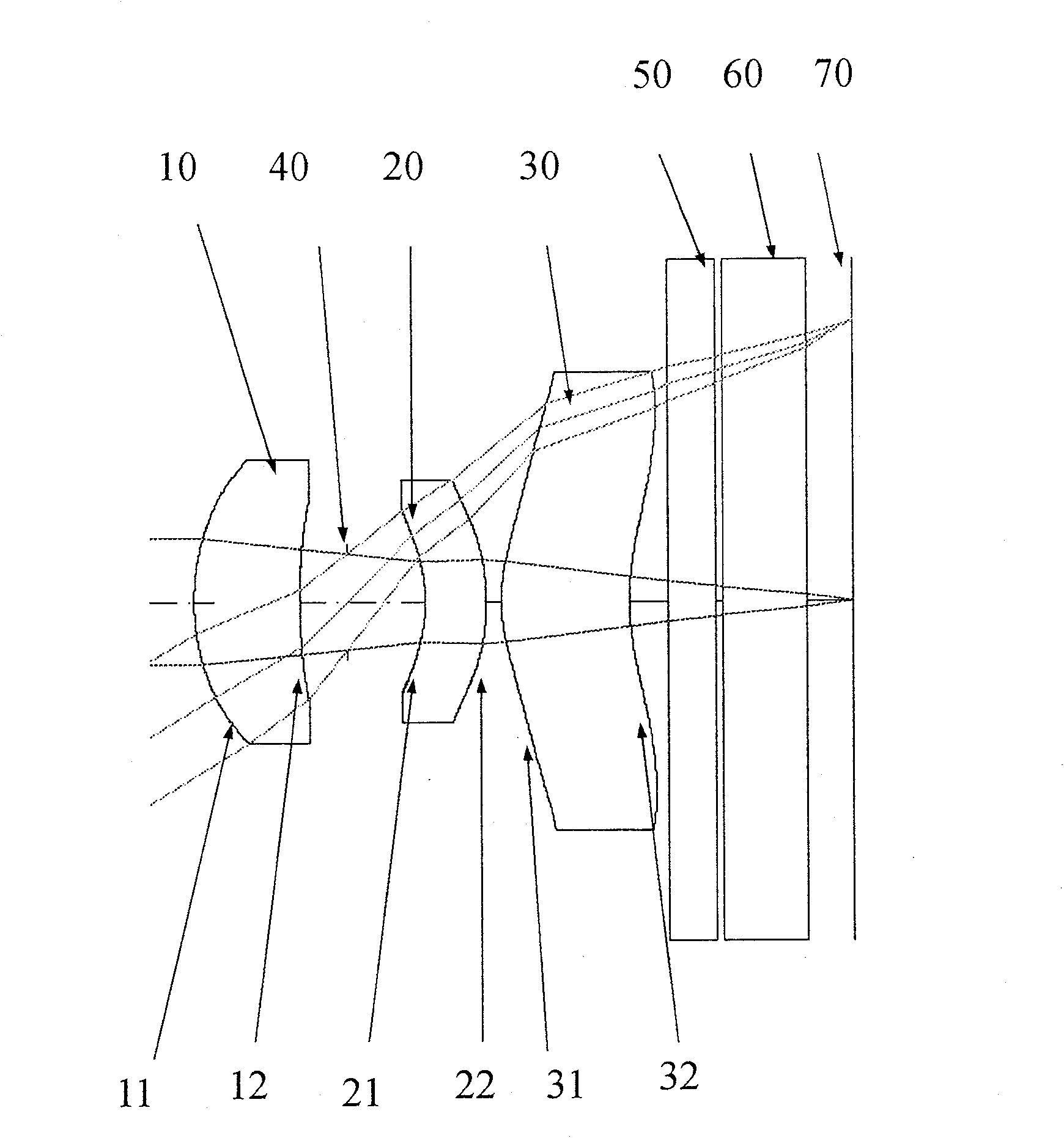
[0074] like figure 1 , the aberration curve of this embodiment is as figure 2 . The imaging lens group is mainly composed of three lenses with refractive power, from the object side to the image side in order:
[0075] A first lens 10 with positive refractive power, the front surface 11 is convex, the rear surface 12 is concave, the material is plastic, and the front surface 11 and the rear surface 12 are aspherical;
[0076] A second lens 20 with negative refractive power, the front surface 21 is concave, the rear surface 22 is convex, the material is plastic, and the front surface 21 and the rear surface 22 are aspherical;
[0077] Also have a third lens 30 with positive refractive power, its front surface 31 is a convex surface, and its rear surface 32 is a concave surface. have an inflection point;
[0078] An aperture 40 of the imaging lens group, located between the first lens 10 and the second lens 20, is used to control the brightness of the imaging lens group;
...
Embodiment 2
[0101] like image 3 , the aberration curve of this embodiment is as Figure 4 . The imaging lens group is mainly composed of three lenses with refractive power, from the object side to the image side in order:
[0102] A first lens 10 with positive refractive power, the front surface 11 is convex, the rear surface 12 is concave, the material is plastic, and the front surface 11 and the rear surface 12 are aspherical;
[0103] A second lens 20 with negative refractive power, the front surface 21 is concave, the rear surface 22 is convex, the material is plastic, and the front surface 21 and the rear surface 22 are aspherical;
[0104] Also have a third lens 30 with positive refractive power, its front surface 31 is a convex surface, and its rear surface 32 is a concave surface. have an inflection point;
[0105] An aperture 40 of the imaging lens group, located between the first lens 10 and the second lens 20, is used to control the brightness of the imaging lens group;
...
PUM
Abstract
The invention relates to an imaging lens group, in particular to a miniaturized imaging lens group applied into a photo mobile phone. The imaging lens group comprises three lenses with refractive power, which from an object side to an image side are a first lens with positive refractive power, a second lens with negative refractive power and a plastic third lens with positive refractive power. The front surface of the first lens is a convex surface; the back surface is a concave surface; and a non-spherical surface is mounted on the front surface. The front surface of the second lens is a concave surface; the back surface is a convex surface; and the non-spherical surfaces are mounted on both the front surface and the back surface. The front surface of the third lens is a convex surface; the back surface is a concave surface; the non-spherical surfaces are mounted on both the front surface and the back surface. Thereinto, the aperture of the imaging lens group is mounted between the first lens and the second lens; in the imaging lens group, the focus of the first lens is f1; the focus of the whole imaging lens group is f; f1 and f satisfy the following relation formula: f / f1 is less than 0.9. With the structure and arrangement mode of the lens of the invention, the size of the lens group is effectively reduced; the sensitivity of the imaging lens group is decreased; and the higher image interpreting power can be obtained.
Description
technical field [0001] The invention relates to an imaging lens group, in particular to a miniaturized imaging lens group applied to a camera phone. Background technique [0002] In recent years, with the rise of mobile phone cameras, the demand for miniaturized photographic lenses has increased day by day, and the photosensitive components of general photographic lenses are only CMOS or CCD. With the gradual development of high-resolution photographic lenses, the requirements for image quality are also increasing. [0003] Common mobile phone lenses mostly adopt a three-element lens structure. The lens structure consists of a first lens with positive refractive power, a second lens with negative refractive power, and a positive refractive power lens from the object side to the image side. The third lens constitutes the so-called Triplet type. In order to correct aberrations, a pre-aperture is generally used, but the configuration of the pre-aperture will increase the stra...
Claims
Application Information
Patent Timeline
Application Date:The date an application was filed.
Publication Date:The date a patent or application was officially published.
First Publication Date:The earliest publication date of a patent with the same application number.
Issue Date:Publication date of the patent grant document.
PCT Entry Date:The Entry date of PCT National Phase.
Estimated Expiry Date:The statutory expiry date of a patent right according to the Patent Law, and it is the longest term of protection that the patent right can achieve without the termination of the patent right due to other reasons(Term extension factor has been taken into account ).
Invalid Date:Actual expiry date is based on effective date or publication date of legal transaction data of invalid patent.

