Supercharge Your Innovation With Domain-Expert AI Agents!

Light source device and projector

A light source device and technology of light source, applied in the direction of light source, electric light source, projection device, etc., can solve the problems of decreased illumination and damage of light source lamp, and achieve the effect of reducing deviation, restraining temperature decrease, and avoiding blackening phenomenon

Inactive Publication Date: 2007-08-22
SEIKO EPSON CORP
View PDF1 Cites 3 Cited by
  • Summary
  • Abstract
  • Description
  • Claims
  • Application Information

AI Technical Summary

Problems solved by technology

Such a blackening phenomenon is the main cause of a decrease in the illuminance of the light source lamp and damage

Method used


Image

  • Light source device and projector
  • Light source device and projector
  • Light source device and projector

Examples


Embodiment Construction

[0026] Hereinafter, embodiments of the present invention will be described based on the drawings.

[0027] "Projector Composition"

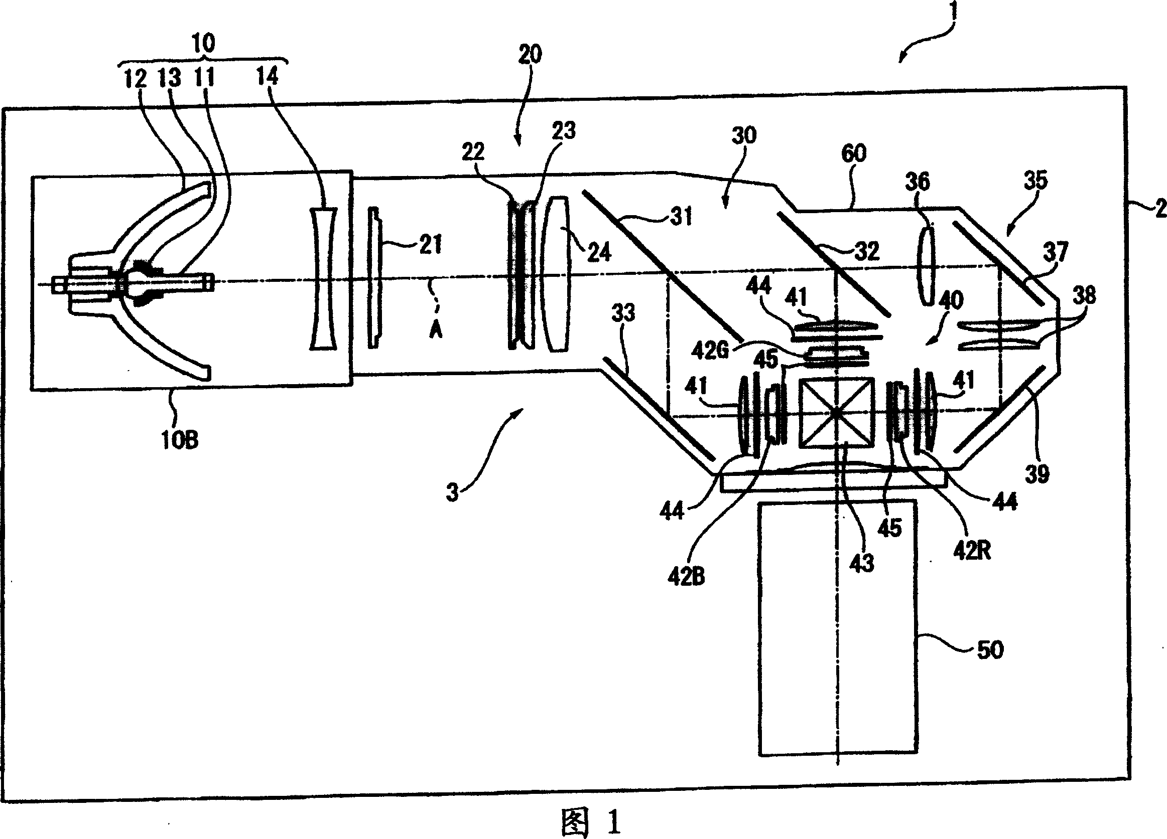
[0028] FIG. 1 is a plan view showing a schematic configuration of a projector 1 in the present embodiment.

[0029] The projector 1 is an optical device that modulates a light beam emitted from a light source according to image information to form image light, and magnifies and projects the image light onto a projection surface such as a screen. As shown in FIG. 1 , the projector 1 is roughly composed of a substantially rectangular parallelepiped exterior case 2 and an optical unit 3 housed and arranged inside the exterior case 2 .

[0030] In addition, although specific illustrations are omitted, in the interior of the exterior case 2, in addition to the optical unit 3, a power supply unit for supplying external power to the constituent members of the projector 1 is arranged, and a power supply unit for supplying power to the projector 1 is pro...


PUM


Abstract

A light source device includes: a light source lamp; a reflector; and a sub-reflection mirror. The light-emitting tube has a light-emitting section having the discharge space therein and sealing sections provided on both sides of the light-emitting section. The sub-reflection mirror is formed in a shape of a bowl that covers the light-emitting section of the light-emitting tube, the sub-reflection mirror having an opening for mounting the sub-reflection mirror to the light-emitting tube by allowing one of the sealing sections of the light-emitting tube to be inserted thereinto. A heat insulating member is provided to at least a part of the light-emitting section and the other one of the sealing sections of the light-emitting tube.

Description

technical field [0001] The present invention relates to a light source device and a projector. Background technique [0002] Conventionally, projectors have been used which modulate light beams emitted from light sources according to image information and enlarge projected optical images. [0003] As such a light source device for a projector, there is known a configuration including: a discharge-type light source lamp such as a metal halide lamp or a high-pressure mercury lamp; a reflector for reflecting a light beam emitted from the light source lamp; The light beam radiated to the front side is reflected by the sub-mirror on the reflector side (for example, refer to the literature: JP-A-2005-148293). [0004] However, as in the light source device described in the literature, when the sub-reflector is attached to the light source lamp, due to the influence of heat generated in the sub-reflector by the irradiated light beam, the heat radiation generated in the light sourc...

Claims


Application Information

Patent Timeline
Patent Type & Authority Applications(China)
IPC IPC(8): F21S2/00F21V7/00F21V29/00G03B21/14F21Y101/00
CPCH01J61/045F21V7/0025H04N5/7441H01J61/86
Inventor 山内健太郎桥爪俊明
Owner SEIKO EPSON CORP
Features
  • R&D
  • Intellectual Property
  • Life Sciences
  • Materials
  • Tech Scout
  • Unparalleled Data Quality
  • Higher Quality Content
  • 60% Fewer Hallucinations
Learn More