Damping floor structure

A floor and structure technology, applied in the field of vibration damping floor structure, to achieve the effects of improving fluidity, improving vibration damping, and improving the ease of filling

Inactive Publication Date: 2007-08-22
NIPPON STEEL & SUMITOMO METAL CORP +1
View PDF4 Cites 8 Cited by
  • Summary
  • Abstract
  • Description
  • Claims
  • Application Information

AI Technical Summary

Problems solved by technology

Therefore, the vibration damping effect is not exhibited corresponding to the filling amount,

Method used


Image

  • Damping floor structure
  • Damping floor structure
  • Damping floor structure

Examples


Example Embodiment

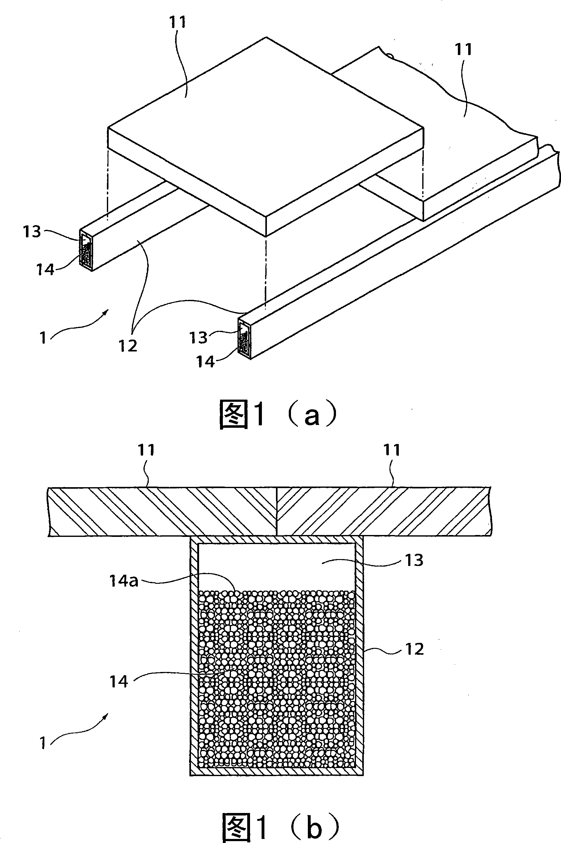
[0052] Hereinafter, as a preferred embodiment for implementing the present invention, a vibration-damping floor structure for suppressing vibration transmitted to the beam supporting the floor will be described in detail with reference to the drawings.

[0053] Fig. 1(a) is a perspective view showing an assembled state of the vibration-damping floor structure 1 to which the present invention is applied, and Fig. 1(b) shows a cross-sectional view of the vibration-damping floor structure 1.

[0054] The vibration-damping floor structure 1 includes a floor 11 and beams 12 supporting the floor 11. In addition, in the vibration damping floor structure 1, a hollow space 13 is formed in the inside of the beam 12, and the powder or granular material 14 is enclosed in the hollow space 13.

[0055] The floor 11 is, for example, a floor used in general residential building structures. As shown in FIG. 1(a), the end is placed on the upper surface of the beam 12 and then screwed with screws su...


PUM

PropertyMeasurementUnit
Angle of reposeaaaaaaaaaa

Abstract

A damping floor structure in which the quality of a powdery/granular material is optimized to easily fill a desired local region with the powdery/granular material, the field work efficiency and the damping performance of a floor are enhanced, and lightweight impact sound is isolated. In the damping floor structure (1) for suppressing vibration of a beam (12) supporting a floor plate (11), a hollow space (13) where the powdery/granular material (14) is placed up to a specified height is formed in the beam (12). The powdery/granular material (14) contains Fe and CaO, and SiO<sub.

Description

technical field [0001] The present invention relates to a vibration-damping floor structure for suppressing vibration transmitted to beams, joists, etc. that support the floor. Background technique [0002] Generally speaking, the floor structure of a building structure such as a house is usually constituted by supporting the floor with framework members such as frames and beams. When impacts associated with walking and working are applied to the floor, vibrations are generated, and the vibrations cause uncomfortable sounds and uncomfortable vibrations. Especially in independent houses or apartments where metal members are used as beams, the vibration and impact sound generated on the floor of the living room or corridor will be directly transmitted to the downstairs, so it is also a source of noise for the occupants downstairs. Cause of great discomfort. [0003] Therefore, particularly in recent years, attempts have been made to suppress vibrations applied to the floor b...

Claims


Application Information

Patent Timeline
IPC IPC(8): E04B5/43E04B1/98E04F15/18
CPCE04B5/10E04B1/84E04F15/18E04F15/20F16F7/015E04B1/98E04B5/43E04F15/225
Inventor 村桥喜满川上宽明杉本明男次桥一树
Owner NIPPON STEEL & SUMITOMO METAL CORP
Why Eureka
Try Eureka