Method for realizing uplink wireless channel resource distribution

A resource allocation and wireless channel technology, which is applied in the LTE field of 3GPP, can solve the problems of single object and no explicit scheduling authorization for different service transmission mechanisms, so as to improve network efficiency and reduce uplink signaling overhead and delay Effect

Active Publication Date: 2007-09-26
HUAWEI TECH CO LTD
View PDF0 Cites 31 Cited by
  • Summary
  • Abstract
  • Description
  • Claims
  • Application Information

AI Technical Summary

Problems solved by technology

[0015] Therefore, there is a problem that the existing technical solutions do not clearly propose the sending mechanism of scheduling

Method used


Image

  • Method for realizing uplink wireless channel resource distribution
  • Method for realizing uplink wireless channel resource distribution

Examples


Example Embodiment

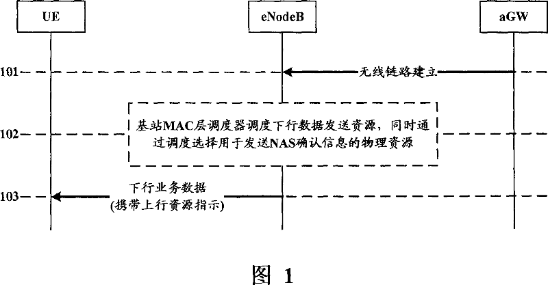
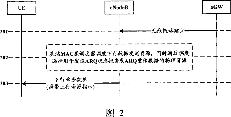
[0027] The method for realizing uplink radio channel resource allocation of the present invention is aimed at the situation that downlink service data requires UE feedback confirmation information (for example, FTP download service). The Node B carries uplink physical resource indication while sending downlink service data, and the uplink physical resource indication is used Then, the uplink physical resource for sending the downlink service data confirmation information is indicated to the UE.

[0028] The uplink physical resource indication may be transmitted in a MAC PDU (Protocol Data Unit, protocol data unit), or may be transmitted on a physical control channel.

[0029] The uplink physical resource indication may include one or more parameters in the time domain, frequency domain, code domain, and transmit power.

[0030] If the UE does not receive an uplink physical resource indication when it needs to send downlink service data confirmation information, it uses a contentio...


PUM


Abstract

The disclosed allocating method for up wireless channel resource comprises: to the down business data, requiring UE to feedback the first data business of down business data ACK message; during sending the down business data, B node carries the first up physical resource indication to UE. Wherein, the first up physical resource indication message can indicate the up physical resource for transmitting the down business data ACK message to the UE. This invention reduces up signaling expending and time delay, and improves network efficiently.

Description

technical field [0001] The present invention relates to LTE (Long Term Evolution, Long Term Evolution) technology of 3GPP (The 3rd Generation Partnership Project, 3rd Generation Partnership Project), especially an implementation method of uplink wireless channel resource allocation therein. Background technique [0002] In the LTE technology of 3GPP, the uplink wireless channel is changed from DCH (Dedicated Channel, dedicated channel) and E-DCH (Enhanced Dedicated Channel, enhanced dedicated channel) of R6 and previous versions to SCH (Shared Channel, shared channel), so the existing In order to implement LTE technology, the network needs to provide a new uplink wireless channel resource allocation and indication mechanism. [0003] In order to solve the above problems, the prior art includes the following solutions. [0004] The first solution is described as follows, which includes the following steps: [0005] Step a, UE (User Equipment, user equipment) requests resour...

Claims


Application Information

Patent Timeline
IPC IPC(8): H04Q7/38H04L1/18H04W72/12
Inventor 余承宇
Owner HUAWEI TECH CO LTD
Why Eureka
Try Eureka