Supercharge Your Innovation With Domain-Expert AI Agents!

Rotor sliding-vane machine

A rotor and mechanical technology, applied in the field of high-pressure rotor sliding vane machinery, can solve the problems of reduced efficiency, no balance, no resistance to changes in the adjacent characteristics of the sealing surface, etc.

Inactive Publication Date: 2011-04-13
亚历山大阿纳托利耶维奇施加诺夫 +1
View PDF10 Cites 0 Cited by
  • Summary
  • Abstract
  • Description
  • Claims
  • Application Information

AI Technical Summary

Problems solved by technology

[0044] All of the above structures are characterized by increased expendable losses reducing their efficiency
The described means of reducing friction through hydraulic balancing of the rotor and movable seals does not produce perfect balancing and is not resistant to changes in the seal surface abutment characteristics of sliding isolation contacts due to the profile of local imperfections and contamination of the working fluid
Even if the change in leakage is insignificant, the impact on volumetric efficiency will lead to a large decrease in mechanical and overall efficiency

Method used


Image

  • Rotor sliding-vane machine
  • Rotor sliding-vane machine
  • Rotor sliding-vane machine

Examples


Embodiment Construction
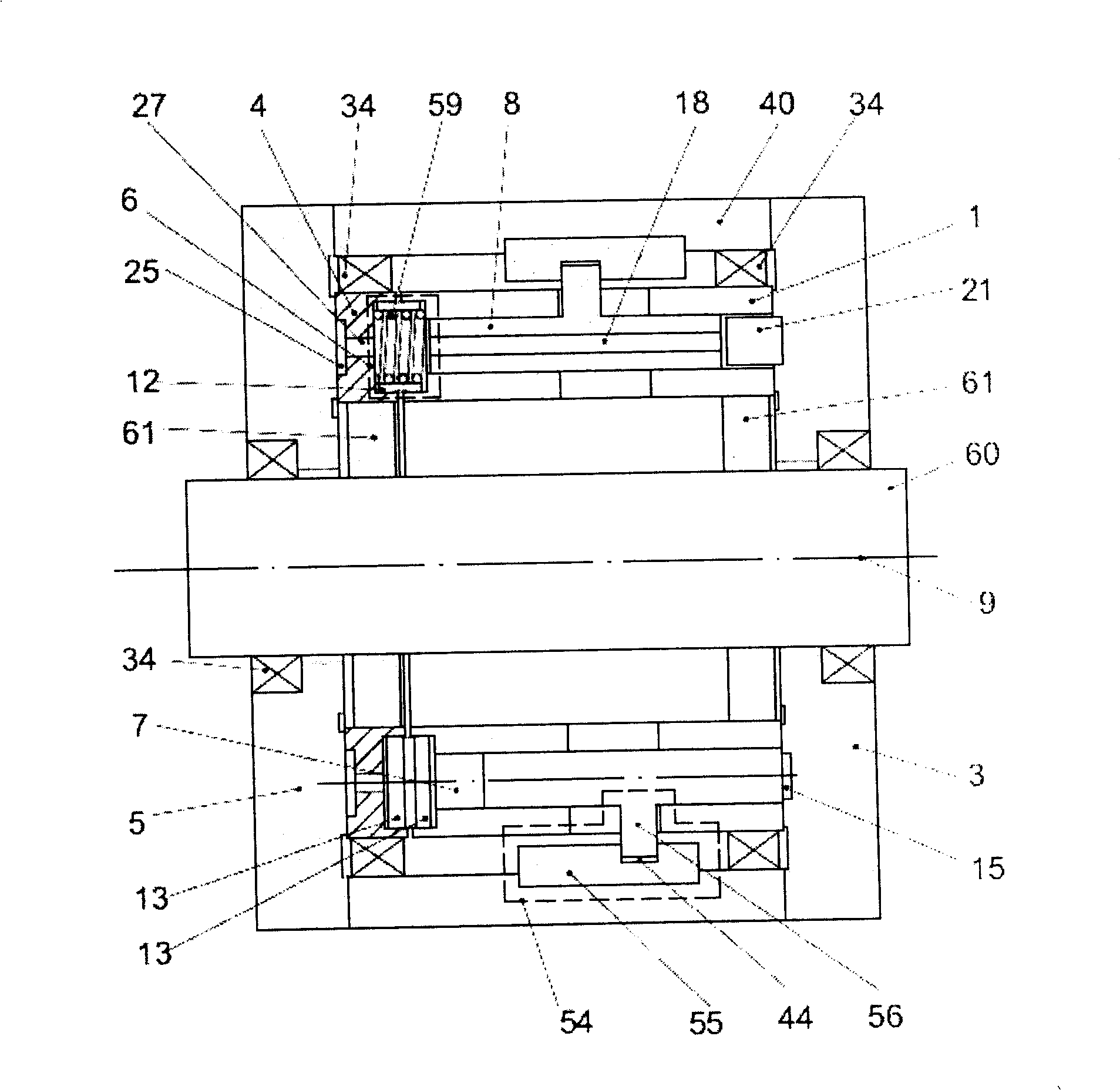
[0082]The basic idea of ​​the invention provides a number of rotor vane mechanical embodiments suitable for use as pumps or hydraulic motors with reversible as well as fixed direction of rotation of the rotor, and as a pump-motor combination for hydromechanical transmissions mechanical embodiment. In some embodiments of the present invention, the housing is fixed on the frame of the unit, and the rotor rotates relative to the housing and the guide rail of the unit. In other embodiments of the invention, the rotor may be fixed to the guide rail of the unit, while the housing rotates relative to it. It is also possible to have an embodiment in which the rotor and housing rotate relative to the rails of the assembly, for example if the rotor machine is a hydromechanical transmission unit. In the following we will consider the relative rotation of the rotor and housing regardless of the type of installation of the rotor machinery in the unit. In any case, a rotor shall mean a un...


PUM


Abstract

A rotor sliding-vane machine comprises a rotor including working (1) and supporting parts (4) connected via force chambers (6) of variable length so that they rotate synchronously with a possibility of little reciprocal axial movements and tilts. The vanes (8) are located in vane chambers (7) of the working part (1) of the rotor and when the rotor is rotating they cyclically change the degree of protrusion into the annular groove (2) made on the face surface of the working part of the rotor. Between the supporting cover plate (5) of the housing and supporting part of the rotor there are supporting cavities hydraulically connected via the means of local pressures balancing to the force chambers of variable length and cavities of the working chamber in the annular groove of the working partof the rotor. Supporting cavities and force chambers of variable length are made so that pressure forces of the working fluid contained in the force chambers significantly balance pressure forces of the working fluid forcing out the working and supporting parts of the rotor from the working and supporting cover plates of the housing providing just a small tightening required for insulation.

Description

technical field [0001] The present invention relates to mechanical engineering and can be used as a high pressure rotor sliding-vane machine capable of operating in pump mode and hydraulic motor mode for greater efficiency and reliability for smooth transfer. Background technique [0002] For smooth conveying and high efficiency, a sliding vane pump should have a working chamber of constant cross-sectional area in the conveying area, low losses in terms of leakage and friction, and be free of cavitation. The above characteristics should be maintained over all operating ranges of displacement variation, pumping pressure and rotor rotational speed, and should also be virtually immune to working fluid contamination and pump element wear. [0003] The working chamber is arranged on the surface of the rotor. For example, in the pump of US570584, to provide a constant cross section required by the working chamber, it is preferable to combine the pump displacement adjustment device...

Claims


Application Information

Patent Timeline
Patent Type & Authority Patents(China)
IPC IPC(8): F04C2/344
CPCF04C2/3448F04C15/0042F04C2/344
Inventor 亚历山大阿纳托利耶维奇施加诺夫叶里米哈伊洛维奇沃克夫
Owner 亚历山大阿纳托利耶维奇施加诺夫
Features
  • R&D
  • Intellectual Property
  • Life Sciences
  • Materials
  • Tech Scout
  • Unparalleled Data Quality
  • Higher Quality Content
  • 60% Fewer Hallucinations
Learn More