Coil locating structure of electronic expansion valve
A technology of electronic expansion valve and positioning structure, which is applied in the direction of valve operation/release device, valve details, valve device, etc., and can solve problems such as product failure, aging of encapsulation layer, coil circumferential positioning and axial positioning failure, etc. , to achieve the effect of resisting high-frequency impact and ensuring normal operation
- Summary
- Abstract
- Description
- Claims
- Application Information
AI Technical Summary
Problems solved by technology
Method used
Image

Examples
Example Embodiment
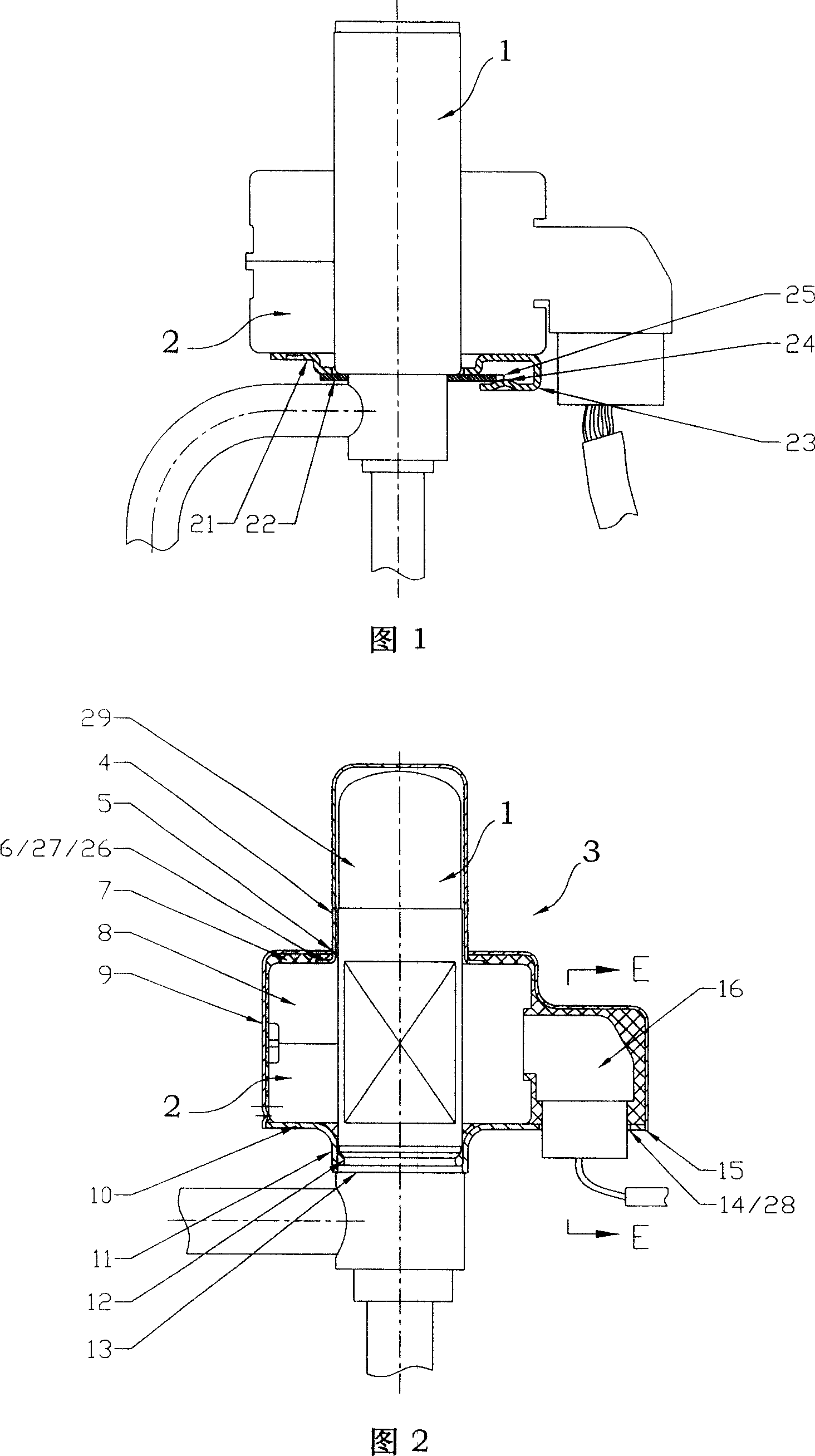
[0032] Example one
[0033] The coil positioning structure of the electronic expansion valve as shown in Fig. 2 includes a valve body 1 and a coil 2. The coil 2 has a winding portion 8 and a socket portion 16, and an axial through hole 5 is provided in the center of the winding portion 8. The hole 5 is sleeved on the valve body 1, and a positioning member is arranged between the coil 2 and the valve body 1. The details are:
[0034] The positioning member includes a bottom plate 10 and an outer cover 3;
[0035] The bottom plate 10 is fixed on the valve body 1 and supports the coil 2;
[0036] The outer cover 3 covers the outside of the coil 2 and has an axial positioning portion 26 corresponding to the bottom plate 10;
[0037] The outer cover 3 is fixedly connected to the bottom plate 10, and the axial positioning portion 26 presses the coil 2 on the bottom plate;
[0038] The bottom plate 10 or the outer cover 3 is provided with a circumferential positioning portion 28 that abu...
Example Embodiment
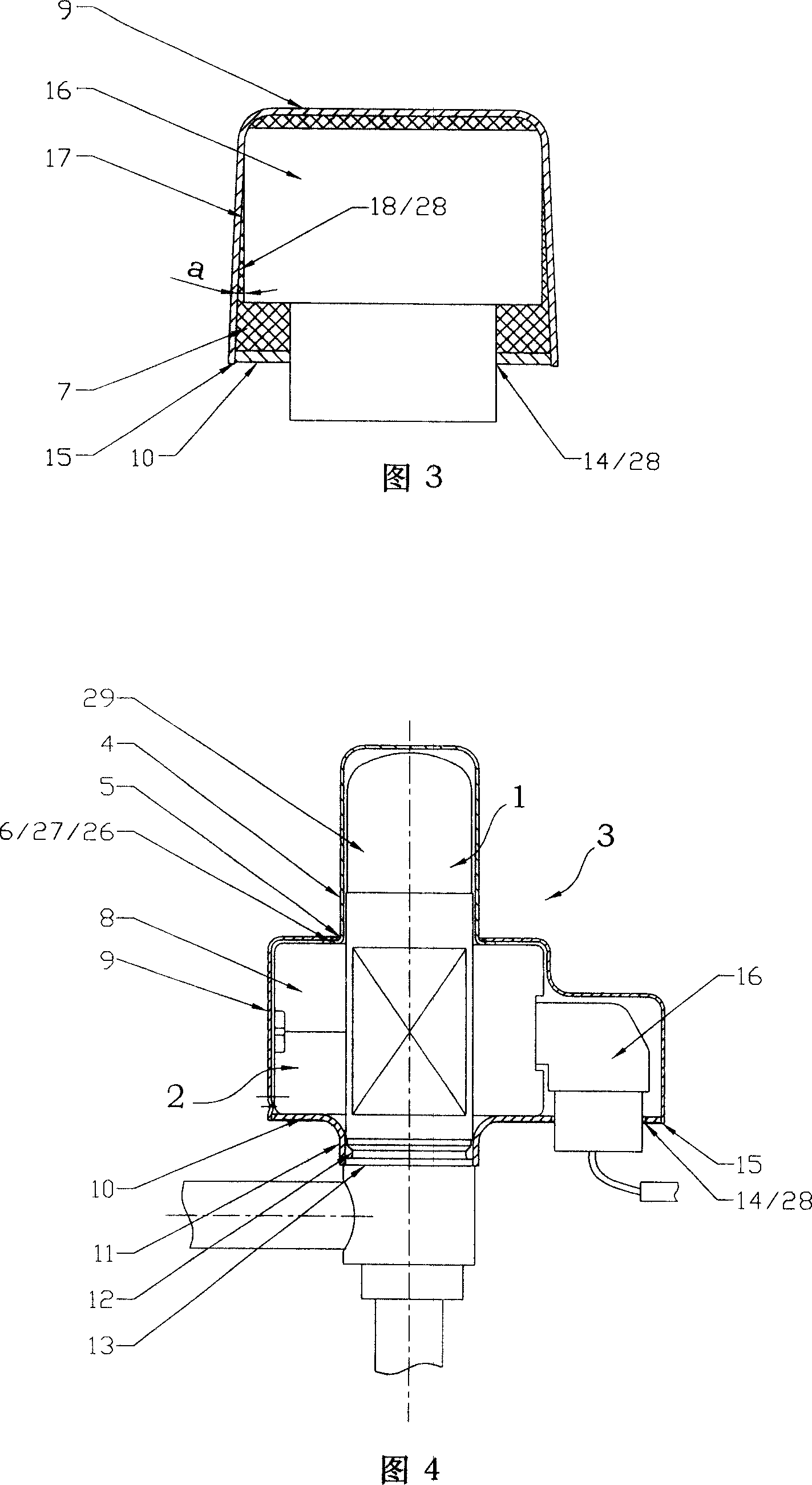
[0045] Example two
[0046] The coil positioning structure of the electronic expansion valve as shown in Fig. 4, on the basis of the structure of the first embodiment, the difference between it and the first embodiment will be explained, and the similarities will not be repeated:
[0047] The pressing portion 27 is an outer flange 6 provided at the lower end of the closure cap 4. The outer flange 6 is located on the lower side of the axial through hole 5 and is pressed against the upper end of the coil by the cover wall at the axial through hole 5, No filler is filled in the gap between the outer cover 3 and the coil 2.
Example Embodiment
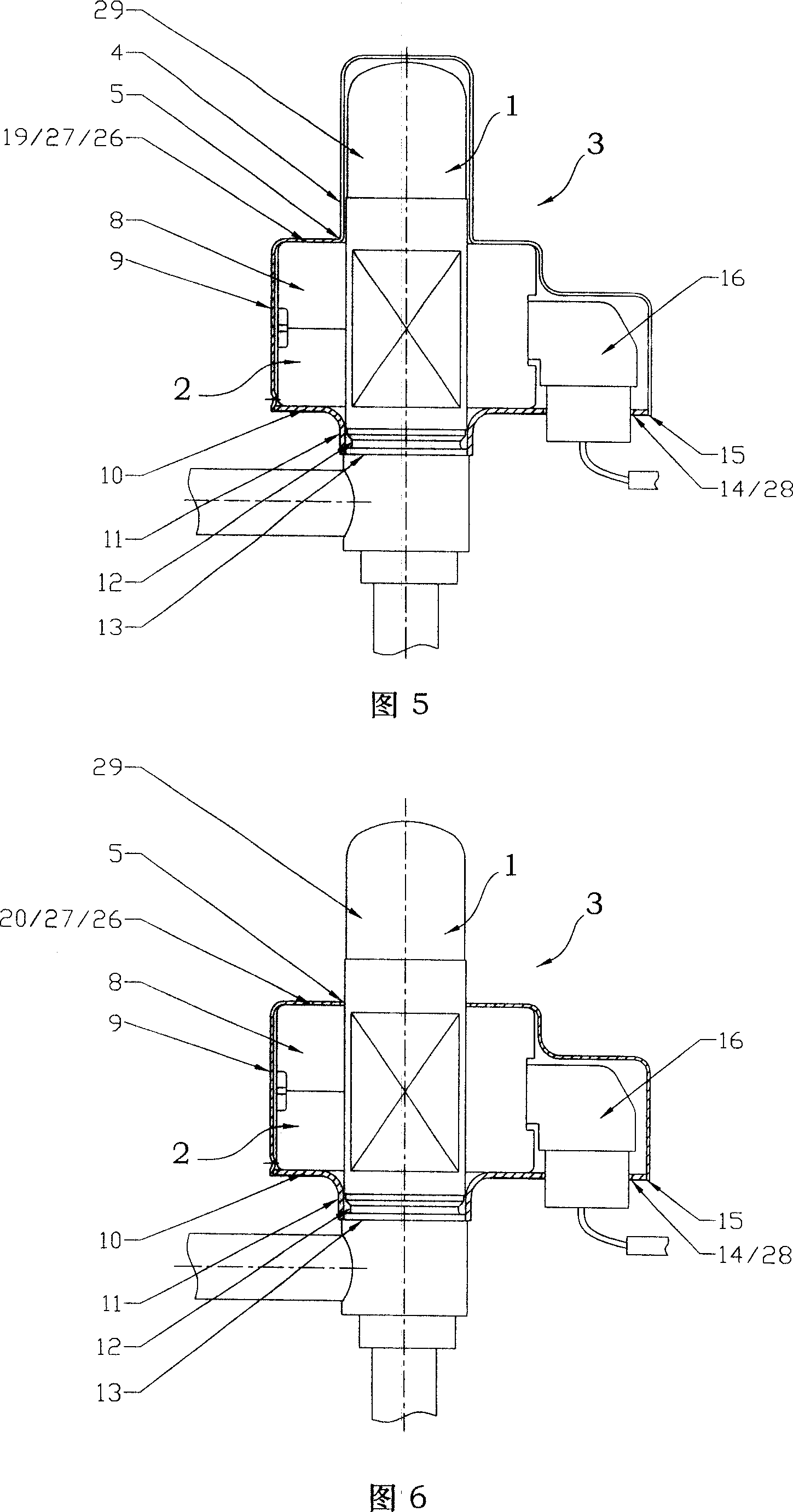
[0048] Example three
[0049] The coil positioning structure of the electronic expansion valve as shown in Fig. 5, based on the structure of the first embodiment, illustrates the difference between it and the first embodiment, and the similarities will not be repeated:
[0050] The outer cover 3 includes a main portion 9 corresponding to the coil 2 and a closing cap 4 extending from the main portion and covered on the protruding section 29. The pressing portion 27 is the plane 20 on which the main portion 9 is pressed on the upper end of the coil 2. The gap between the coils 2 is not filled with filler.
PUM
 Abstract
Description
Claims
Application Information
 - R&D Engineer
- R&D Manager
- IP Professional
- Industry Leading Data Capabilities
- Powerful AI technology
- Patent DNA Extraction
Browse by: Latest US Patents, China's latest patents, Technical Efficacy Thesaurus, Application Domain, Technology Topic.
© 2024 PatSnap. All rights reserved.Legal|Privacy policy|Modern Slavery Act Transparency Statement|Sitemap