Check patentability & draft patents in minutes with Patsnap Eureka AI!

Supporting structure for separator of spinning machine

A support structure, separator technology, applied in spinning machine, continuous winding spinning machine, textile and paper making, etc., can solve problems such as damage, separator deformation, etc.

Active Publication Date: 2011-04-20
TOYOTA IND CORP
View PDF1 Cites 0 Cited by
  • Summary
  • Abstract
  • Description
  • Claims
  • Application Information

AI Technical Summary

Problems solved by technology

When the above impact load is applied to the separator, the separator can be deformed or damaged

Method used


Image

  • Supporting structure for separator of spinning machine
  • Supporting structure for separator of spinning machine
  • Supporting structure for separator of spinning machine

Examples


Embodiment Construction

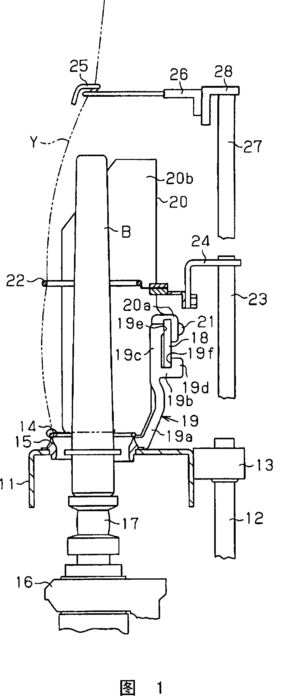
[0024] Hereinafter, a preferred embodiment of a separator support structure in the form of a separator rod in a ring spinning machine according to the present invention will be described with reference to FIGS. 1 to 4B. Referring to accompanying drawing 1, this ring spinning machine has a ring bar 11, and it is fixed on the upper part of support 12 by bracket 13, and support 12 ascends and descends by means of a lifting mechanism (not shown). A ring 15 guiding the traveler 14 of each spindle 17 is fixed in a hole in the ring plate 11 , a plurality of such rings 15 are arranged at equal intervals, and the spindles are supported by means of spindle rails 16 .

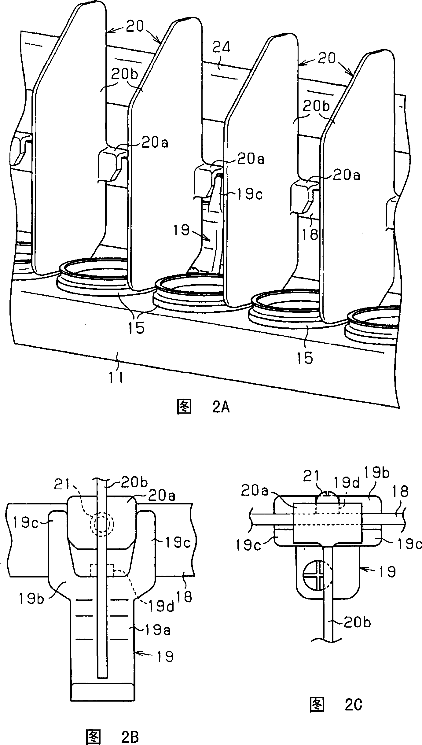
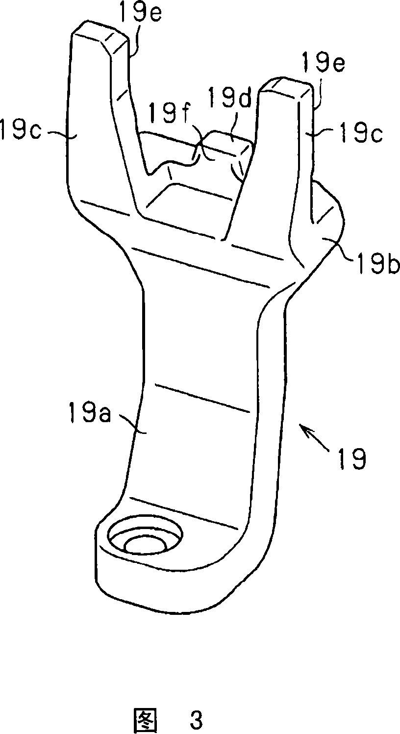
[0025] Referring to accompanying drawing 1 and 2A, separator rod support 19 is fixed on the position of ring plate 11 and is positioned at the rear portion of ring plate 11 by screw, is used for supporting separator rod 18, and separator rod 18 is along the ring plate 11. Extended vertically. According to Figure 2A, a pl...


PUM


Abstract

The invention provides a support structure for a separator of the spinning machine which has a ring rail. The separator and the ring rail rise and fall simultaneously. The support structure is characterized in that the support can incline backward from its normal position when driven by any external force. The back of the support is equipped with a restriction element which is used for limiting the center of gravity of the separator before the backward lean fulcrum of the separator.

Description

technical field [0001] The present invention relates to support structures for separators of spinning machines such as ring spinning machines, ring twisting machines and similar machines. Background technique [0002] In a spinning machine such as a ring spinning machine, ring twisting machine and similar machines, the yarn fed from the front roller is guided through the holes of the guide hooks mounted on the guide hook plate and wound On the bobbin, at the same time, the yarn guide hole of the yarn guide hook is used as the center of the balloon to rotate. Set an air pattern control ring (or a balloon control ring) for each spindle of the spinning machine to limit the balloon, and set a separator between any two adjacent spindles to prevent the yarn from occurring at one spindle End breaks extended to other spindles. [0003] The separator can be supported in two different ways. One way is that a plurality of separators are fixed on the separator rods at predetermined i...

Claims


Application Information

Patent Timeline
Patent Type & Authority Patents(China)
IPC IPC(8): D01H1/42D01H7/18
Inventor 林久秋新美究藤井能理石井隆久
Owner TOYOTA IND CORP
Features
  • R&D
  • Intellectual Property
  • Life Sciences
  • Materials
  • Tech Scout
  • Unparalleled Data Quality
  • Higher Quality Content
  • 60% Fewer Hallucinations
Learn More