Supercharge Your Innovation With Domain-Expert AI Agents!

Heat conduction bus, particularly for a microprocessor-based computation unit

A computing unit and microprocessor technology, which is applied in the direction of assembling printed circuits, electrical components, and electrical solid devices with electrical components, and can solve problems such as inability to ensure soldering, disconnection, etc.

Inactive Publication Date: 2008-05-28
SIEMENS VDO AUTOMOTIVE CORP
View PDF0 Cites 0 Cited by
  • Summary
  • Abstract
  • Description
  • Claims
  • Application Information

AI Technical Summary

Problems solved by technology

[0006] In fact, at present, it is clear that these difficulties are often directly caused by the welding strips (especially the preheating temperature), which cannot ensure the planned correct welding of the protrusion closest to the collector
[0007] The result of this is that a considerable number of protrusions are actually simply glued to the corresponding terminals, rather than being properly soldered to them, with the result that there is a risk of disconnection

Method used


Image

  • Heat conduction bus, particularly for a microprocessor-based computation unit

Examples


Embodiment Construction

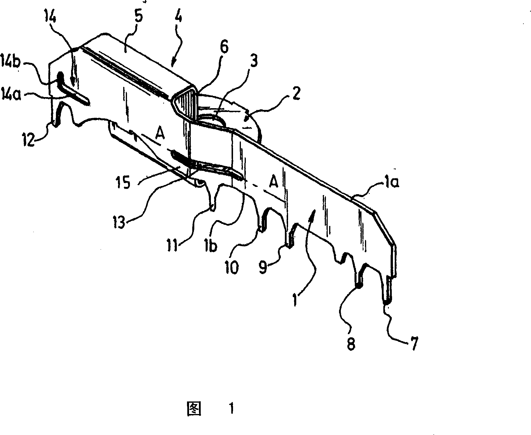
[0019] The thermally conductive bus according to the invention, represented by the example in FIG. 1, is to be connected to a motor vehicle battery, on the one hand to provide power to electronic components, in particular computing units based on microprocessors, and on the other hand to evacuate them from these The heat energy generated by the element.

[0020] In general, this bus comprises a strip 1 formed of a substantially flat plate having a generally parallelepiped shape, delimited in particular by two parallel longitudinal sides 1a and 1b.

[0021] The bus also includes ring terminals 2 with holes 3 for mounting to battery terminals. The ring terminal 2, extending in a plane perpendicular to the strip 1, is connected to one of its longitudinal sides 1a by an L-shaped connection or collector 4 (reversed L in FIG. 1 ), close to said longitudinal side, the collector consists of:

[0022] - a wing 5 attached to the longitudinal edge 1a and perpendicular to the plane of t...


PUM


Abstract

The bus has a thermal conducting strip (1) equipped with connecting tabs (7-12) connected to a bonding pad of electronic components subjected to heat. A collector (4) is integrated with the strip and disposed in a manner to canalize and evacuate the thermal energy drained by the tabs and transited by the strip. Slots (13, 14) are arranged in the strip near to the tabs and opposite to the tabs (11, 12) close to the collector to interpose the slots between the tabs and collector to form an obstacle opposing to direct path of the thermal energy between the tabs (11, 12) and the collector.

Description

technical field [0001] The present invention relates to a thermally conductive bus, especially for use in microprocessor-based computing units. [0002] In particular, the present invention aims to provide a thermally conductive bus, starting from a single starting end, comprising a thermally conductive strip with a plurality of protrusions soldered to terminals of electronic components that may become hot, and connected to the strip The collectors are arranged to guide and dissipate the thermal energy discharged by the protrusions and flow through the strip. Background technique [0003] Such buses are used in particular in the automotive sector as heat sinks to dissipate the thermal energy generated by the electronic components of the printed circuit. [0004] One of the obstacles encountered with such a bus is that, during the welding operation, it is difficult to achieve a compromise of welding operation parameters (preheat time and temperature, welding time, etc.) to e...

Claims


Application Information

Patent Timeline
Patent Type & Authority Applications(China)
IPC IPC(8): H05K7/20H05K3/34H01L23/367
CPCH05K1/0263H01L2924/0002H01L23/3672H05K3/301H05K2201/10272H05K2201/10037H01L2924/00
Inventor P·加丁
Owner SIEMENS VDO AUTOMOTIVE CORP
Features
  • R&D
  • Intellectual Property
  • Life Sciences
  • Materials
  • Tech Scout
  • Unparalleled Data Quality
  • Higher Quality Content
  • 60% Fewer Hallucinations
Learn More