Spindle head water cooling system

A spindle head, water cooling technology, applied in metal processing machinery parts, maintenance and safety accessories, metal processing equipment, etc., can solve the problems of oil leakage, difficult to clean, easy waste of maintenance energy, etc., to achieve high efficiency and low manufacturing cost , the effect of simple and reasonable structure

Inactive Publication Date: 2008-06-04
郑森法
View PDF0 Cites 7 Cited by
  • Summary
  • Abstract
  • Description
  • Claims
  • Application Information

AI Technical Summary

Problems solved by technology

[0003] The present invention mainly solves technical problems such as oil leakage, difficult cleaning, easy maintenance and waste of en

Method used


Image

  • Spindle head water cooling system
  • Spindle head water cooling system

Examples


Example Embodiment

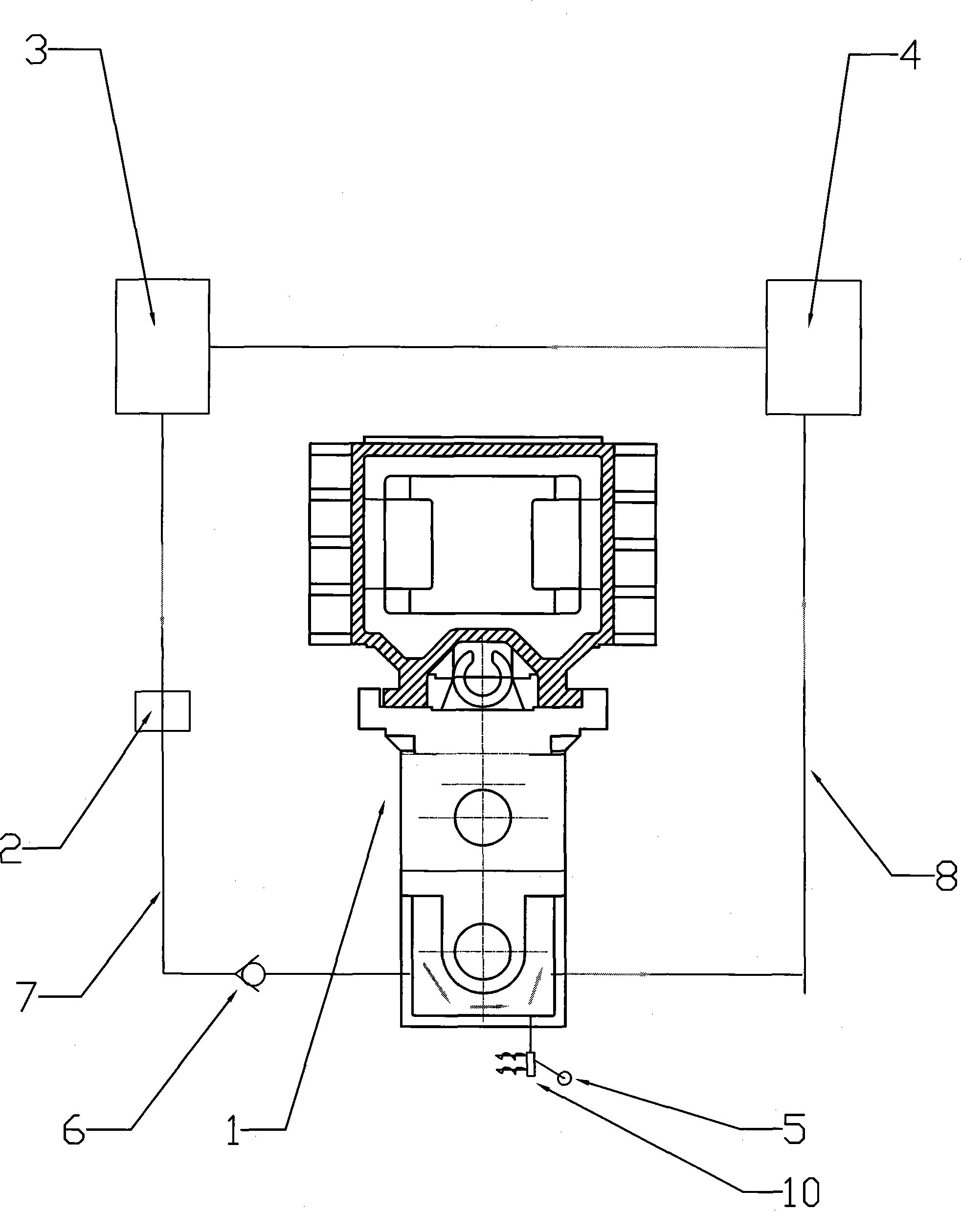
[0015] Example: According to figure 1 The present invention shown is mainly made up of spindle head 1, water pump 2, water storage tank 3, recovery water tank 4, water inlet pipe 7, water outlet pipe 8, one-way valve 6 and manual switch 5.

[0016] like figure 1 As shown, a water storage tank 3 and a recovery water tank 4 are arranged on a high-grade numerically controlled machine tool, and the two water tanks are connected through pipelines. The pipeline 8, the recovery pipeline 8 is connected to the output pipe of the spindle head 1,

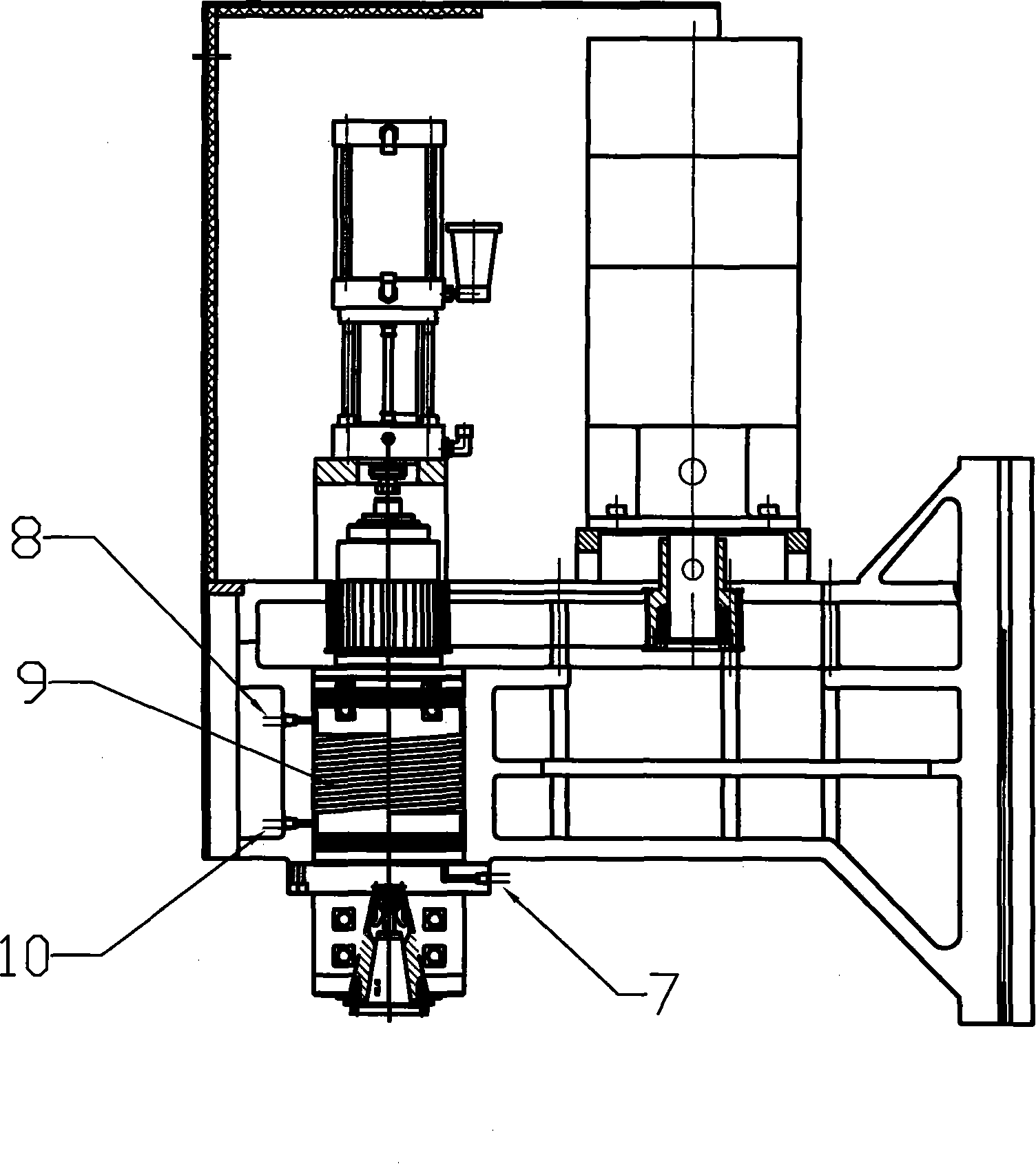
[0017] like figure 2 As shown, the main shaft head 1 is composed of a main shaft and a main shaft sleeve. A spiral channel 9 is arranged around the main shaft in the main shaft sleeve. One end of the spiral channel is connected with a water inlet pipe 7, and the other end is connected with a water outlet pipe 8. The water inlet pipe 7 and the The water storage tank 3 is connected, and the outlet pipe 8 is connected with the recovery water ...


PUM


Abstract

The invention provides a main shaft head water cooling system, comprising a water tank, a pipe, a mainshaft and a water pump. The invention is characterized in that the main shaft head consists of a mainshaft and a mainshaft sleeve; a spiral passage is arranged between the mainshaft and the main shaft sleeve; one end of the spiral passage is connected with a water inlet pipe; the other end of the spiral passage is connected with a water outlet pipe; furthermore, at least one water tank is respectively connected with the water inlet pipe and the water outlet pipe; the water tank, the water inlet pipe, the water outlet pipe and the main shaft head constitute an enclosed circulation system together. Therefore, the invention has the advantages of simple and reasonable structure, high benefit, low manufacturing cost, etc.

Description

technical field [0001] The invention relates to a cooler, in particular to a water cooling system for cooling the temperature of the spindle head of a high-grade numerical control machine tool. Background technique [0002] In high-end CNC machine tools, due to the high-speed operation of the spindle, thermal displacement will occur on the spindle head. The thermal displacement not only reduces the life of the spindle and the precision of the spindle, but also produces noise and vibration due to the damage of the precision of the spindle bearing. The general concern of manufacturers and users. At present, high-end CNC machine tools generally adopt the spindle oil temperature control system. Although this spindle oil temperature control system (oil cooler system) solves this problem, the system has the possibility of oil leakage and the possibility of fire; The working environment is not easy to clean, and it is prone to failure, maintenance is relatively difficult, energy i...

Claims


Application Information

Patent Timeline
IPC IPC(8): B23Q11/12
Inventor 郑森法
Owner 郑森法
Why Eureka
Try Eureka