Check patentability & draft patents in minutes with Patsnap Eureka AI!

Motion control device for vehicle

A technology for motion control devices, vehicles, applied in directions such as brakes

Inactive Publication Date: 2008-06-25
ADVICS CO LTD
View PDF5 Cites 2 Cited by
  • Summary
  • Abstract
  • Description
  • Claims
  • Application Information

AI Technical Summary

Problems solved by technology

However, the influence exerted on the yaw rate sensor by vibration generated by actuation of a pump (reciprocating type) as a hydraulic device cannot be sufficiently reduced

Method used


Image

  • Motion control device for vehicle
  • Motion control device for vehicle
  • Motion control device for vehicle

Examples


no. 1 approach

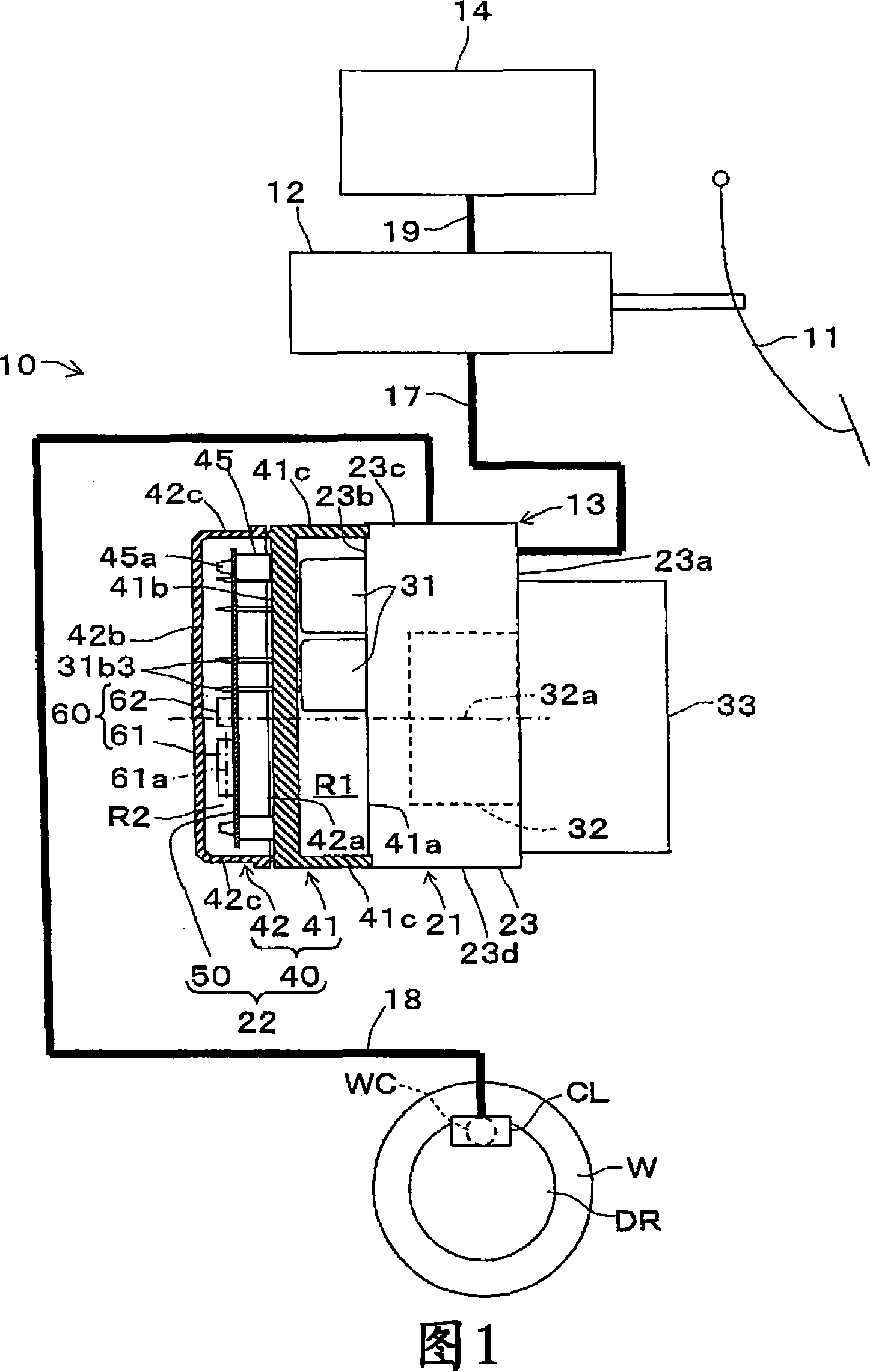
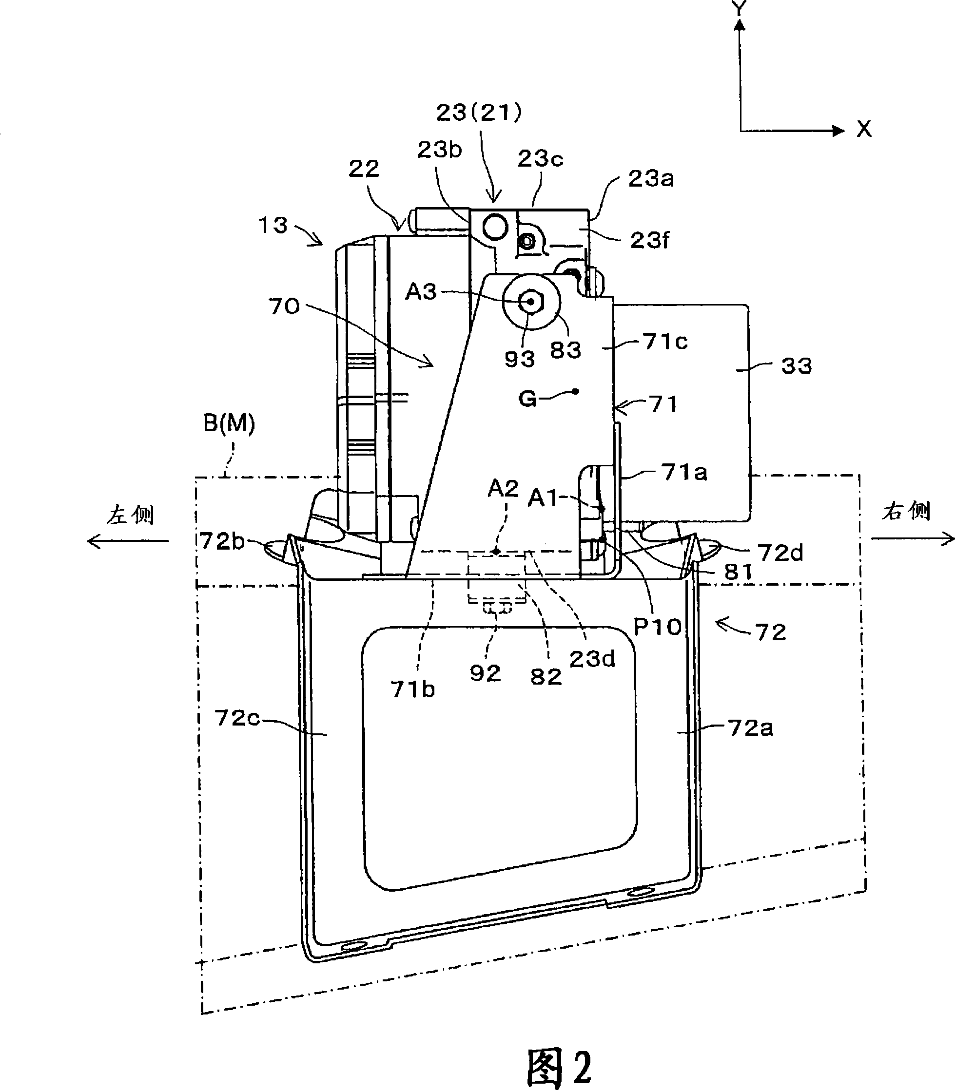
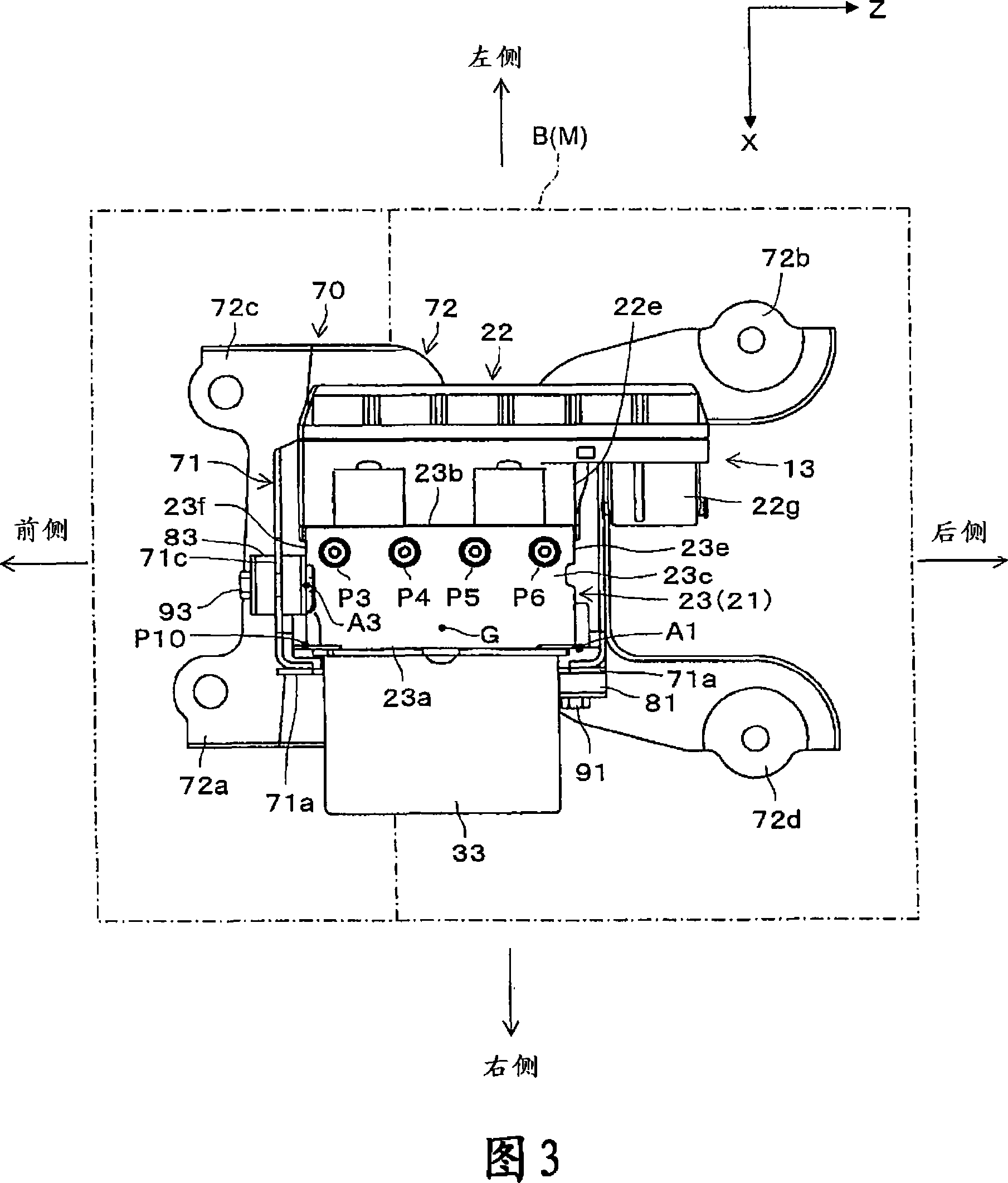
[0025] Hereinafter, a first embodiment of a motion control device for a vehicle according to the present invention will be described with reference to the drawings. FIG. 1 shows a schematic diagram of a hydraulic braking system 10 including a motion control device 13 . FIGS. 2 to 4 each show a front view, a top view, and a side view of the motion control device 13 supported on the body B of the vehicle M through the bracket 70 .

[0026] The hydraulic braking system 10 applies a braking force to wheels W of the vehicle M (only one is shown in the figure for simplicity). As shown in FIG. 1 , a hydraulic braking system 10 is provided with a master cylinder 12 , wheel cylinders WC (only one is shown in the figure for brevity), a motion control device 13 and a fluid storage tank 14 .

[0027] Master cylinder 12 generates hydraulic pressure (base hydraulic pressure) in accordance with a brake manipulation state by depressing brake pedal 11 , and applies the hydraulic pressure to w...

no. 2 approach

[0090] The present invention may not be applied to a motion control device with a rotary pump for a vehicle, but may be applied to a motion control device with a piston pump. This modification or second embodiment will be described below with reference to FIGS. 8 to 10 . FIG. 8 is a schematic front view, partly in section, of a hydraulic brake system 10 provided with a motion control device 13 with a piston pump 132 for a vehicle M. As shown in FIG. FIG. 9 is a right side view of the hydraulic brake system 10 , and FIG. 10 is a partial sectional view showing the piston pump 132 .

[0091] Specifically, the pump 132 as a piston pump includes: a pump drive part 132b driven to rotate by the motor 33, and a plurality of (for example, two in this specific embodiment) pumps that complete the pump function with the rotation of the pump drive part 132b. sending part 132c.

[0092] As mainly shown in FIGS. 9 and 10 , the pump driving portion 132b is provided with an eccentric cam 132...


PUM


Abstract

A motion control device for a vehicle is configured so that a hydraulic unit mounting therein a pump for generating a controlled hydraulic pressure applied to respective wheel cylinders of the vehicle is integrated with a control unit provided with a yaw rate sensor for detecting a yaw rate of the vehicle and capable of controlling the hydraulic unit. The pump is composed of a pump drive section, drivingly rotated by a motor, and pumping sections which perform a pump function with the rotation of the pump drive section. The yaw rate sensor, the motor and the pump are arranged to satisfy a positional relation that the extending direction of a detection axis of the yaw rate sensor does not coincide with both of the extending directions of a rotational axis of the motor and a rotational axis of the pump drive section.

Description

[0001] import by reference [0002] This application is based on and claims priority under 35 U.S.C 119 with respect to Japanese Application No. 2006-339980 filed December 18, 2006 and Japanese Application No. 2007-291864 filed November 9, 2007, which are hereby incorporated by reference Its entire content is incorporated herein. technical field [0003] The present invention relates to a motion control device for a vehicle, which integrally includes a hydraulic unit in which a pump for generating controlled hydraulic pressure applied to each wheel cylinder of the vehicle is installed, and a control unit provided with a control unit for detecting The yaw rate sensor of the yaw rate and can control the hydraulic unit. Background technique [0004] Hitherto, a motion control device for a vehicle shown in International Publication WO 2005 / 039946A1 (hereinafter referred to as Patent Document 1) is known. As shown in FIGS. 1 and 2 of Patent Document 1, the motion control device...

Claims


Application Information

Patent Timeline
Patent Type & Authority Applications(China)
IPC IPC(8): B60T8/1755
Inventor 神谷雅彦宇佐美忠庆
Owner ADVICS CO LTD
Features
  • R&D
  • Intellectual Property
  • Life Sciences
  • Materials
  • Tech Scout
  • Unparalleled Data Quality
  • Higher Quality Content
  • 60% Fewer Hallucinations
Learn More