Fuel feed apparatus and accumulator fuel injection system having the same
A fuel injection system and fuel supply technology, applied in the direction of charging system, liquid fuel feeder, mechanical equipment, etc., can solve the problem of fuel supply equipment becoming larger
- Summary
- Abstract
- Description
- Claims
- Application Information
AI Technical Summary
Problems solved by technology
Method used
Image


Examples
no. 1 example
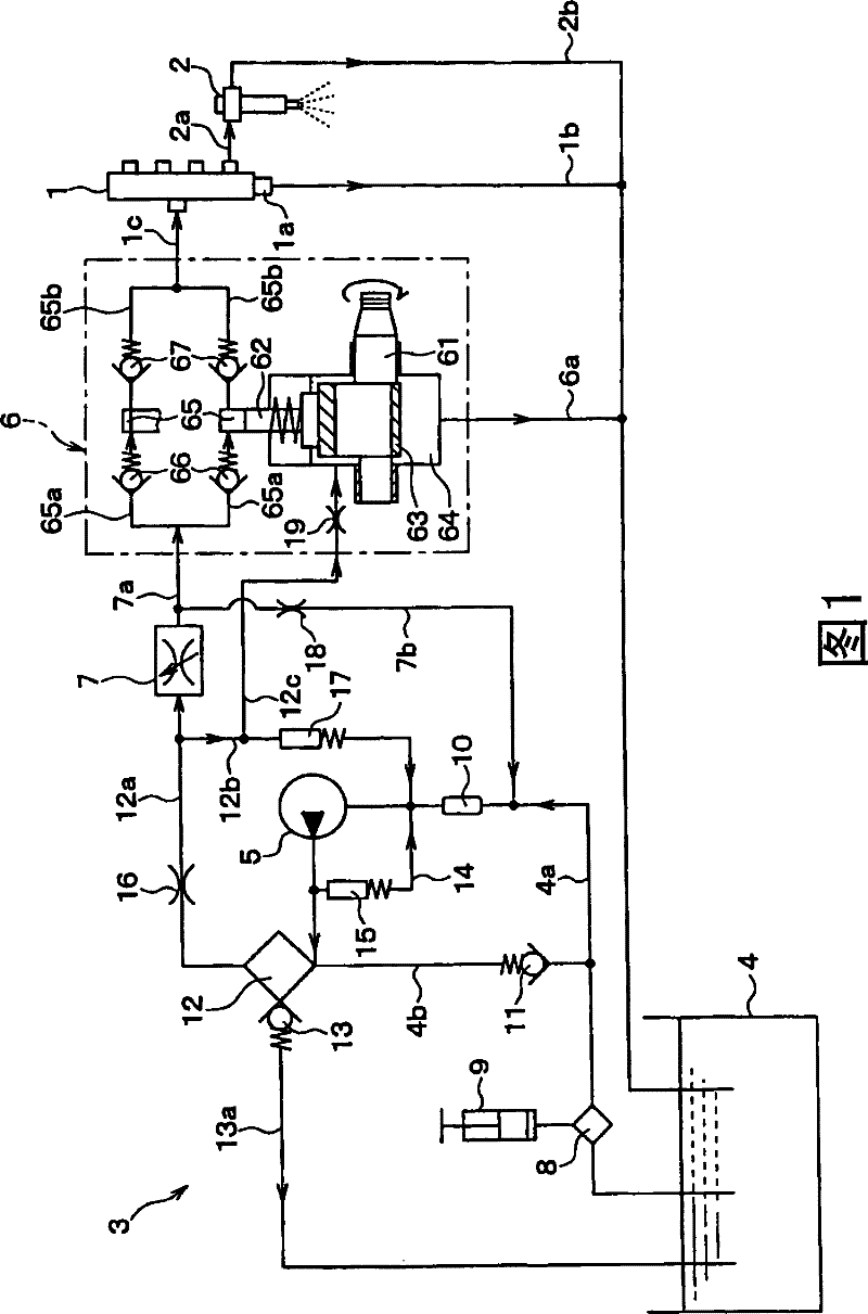
[0021] The following will refer to figure 1 The first embodiment is described.
[0022] The accumulator fuel injection system is applied to, for example, a four-cylinder diesel engine. The accumulator fuel injection system includes: a common rail 1 for accumulating high-pressure fuel; an injector 2 for injecting high-pressure fuel from the common rail 1 into the combustion chamber of the diesel engine; and a fuel supply device 3 for High-pressure fuel is supplied into the common rail 1 .
[0023] Common rail 1 functions as a pressure accumulation unit for accumulating high-pressure fuel supplied from fuel supply device 3 and for containing the high-pressure fuel at a target common-rail pressure. A control unit (ECU), not shown, determines the target common rail pressure according to operating conditions such as the throttle position of the accelerator pedal and the rotational speed of the diesel engine.
[0024] The common rail 1 is provided with a pressure limiter 1a that ...
no. 2 example
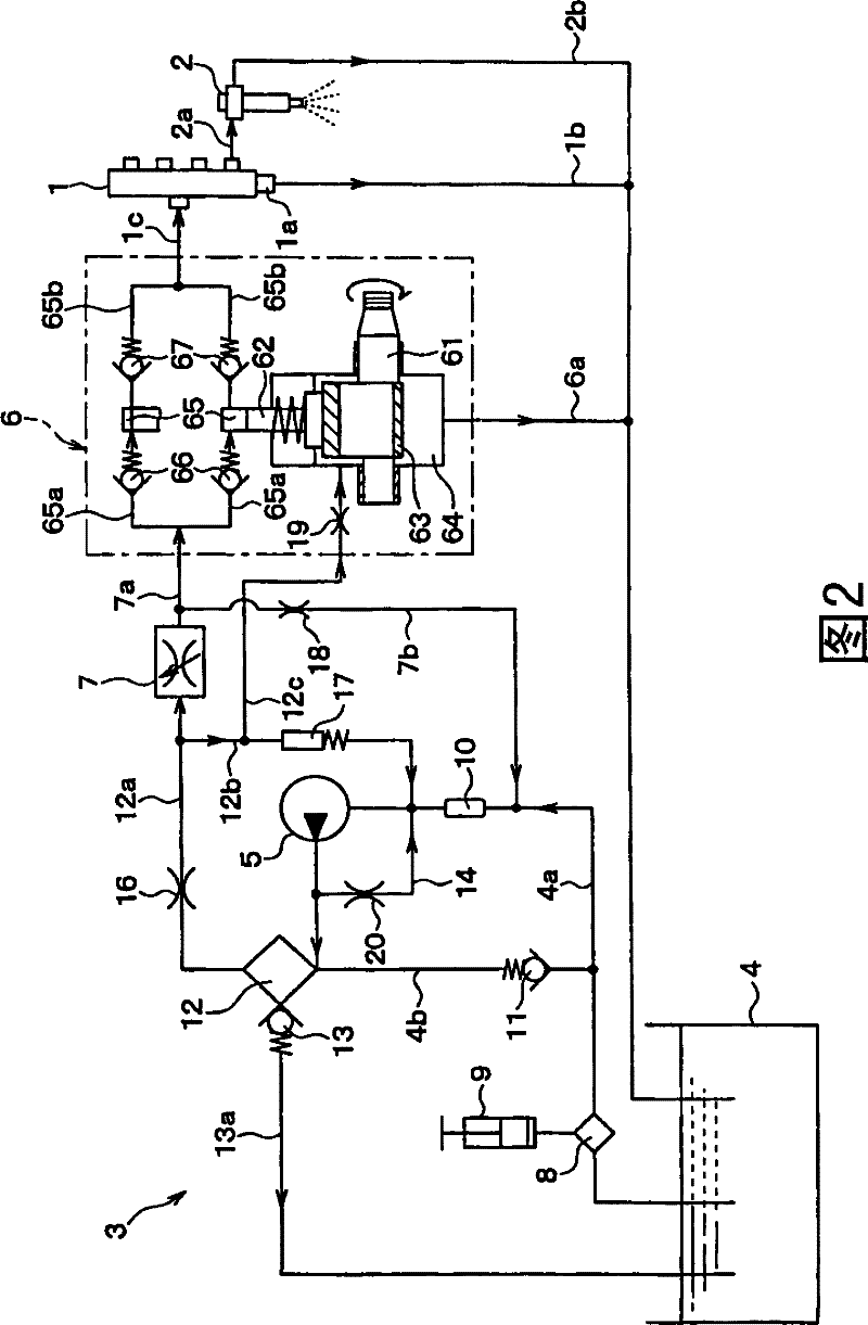
[0060] In this example, as figure 2 As shown, the orifice 20 is configured to function as a backflow control unit.
[0061] Orifice 20 is a fixed throttling device for reducing the fuel pressure downstream of feed pump 5 . The capillary can be used as a fixed throttling device to function as a backflow control unit. In this embodiment, the orifice 20, i.e. the return control unit, is provided to the return channel 14, so that the amount of fuel returned through the return channel 14 can be correspondingly increased, thereby increasing the upstream of the feed pump 5 and the downstream of the feed pump 5. pressure difference between.
[0062] In this structure, as the fuel pressure downstream of the feed pump 5 increases to a predetermined pressure at which the pressure reducing valve 13 opens, the amount of fuel returned through the return passage 14 can be increased. The structure of the fuel supply device other than the features of this embodiment is basically the same a...
no. 3 example
[0065] exist image 3 In this embodiment shown, a breather valve 21 is provided to the fuel supply device in the first embodiment for discharging gas accumulated in the fuel supply passage.
[0066] The vent valve 21 has a structure similar to that of the pressure reducing valve 13 . The vent valve 21 is provided at a position downstream of the feed pump 5 where gas easily accumulates. Specifically, the breather valve 21 is provided, for example, at a vertical upper portion of a housing housing the fuel filter 12 .
[0067] In addition, the breather valve 21 is opened at a predetermined pressure which is equal to or lower than the allowable pressure of the fuel filter 12 and which is lower than the predetermined pressure at which the pressure reducing valve 13 is opened. When the fuel pressure downstream of the feed pump 5 increases so that the breather valve opens, the gas accumulated in the fuel passage returns to the fuel tank 4 through the fuel pipe 13 a together with th...
PUM
 Abstract
Description
Claims
Application Information
 - R&D
- Intellectual Property
- Life Sciences
- Materials
- Tech Scout
- Unparalleled Data Quality
- Higher Quality Content
- 60% Fewer Hallucinations
Browse by: Latest US Patents, China's latest patents, Technical Efficacy Thesaurus, Application Domain, Technology Topic, Popular Technical Reports.
© 2025 PatSnap. All rights reserved.Legal|Privacy policy|Modern Slavery Act Transparency Statement|Sitemap|About US| Contact US: help@patsnap.com