Electric control circuit apparatus for relay

A relay circuit and electrical control technology, applied in relays, circuits, electrical components, etc., can solve the problems of energy waste, increase energy consumption of electronic switch circuits, and large circuit currents, achieve a wide range of applications, save energy consumption, The effect of reducing quiescent current

Inactive Publication Date: 2008-07-23
西蒙电子商务(中国)有限公司
View PDF0 Cites 1 Cited by
  • Summary
  • Abstract
  • Description
  • Claims
  • Application Information

AI Technical Summary

Problems solved by technology

Whether it is static or after the relay is closed, the circuit current is relatively large, which increases th

Method used


Image

  • Electric control circuit apparatus for relay
  • Electric control circuit apparatus for relay

Examples


Example Embodiment

[0025] In order to understand the technical content of the present invention more clearly, the following embodiments are given for detailed description.

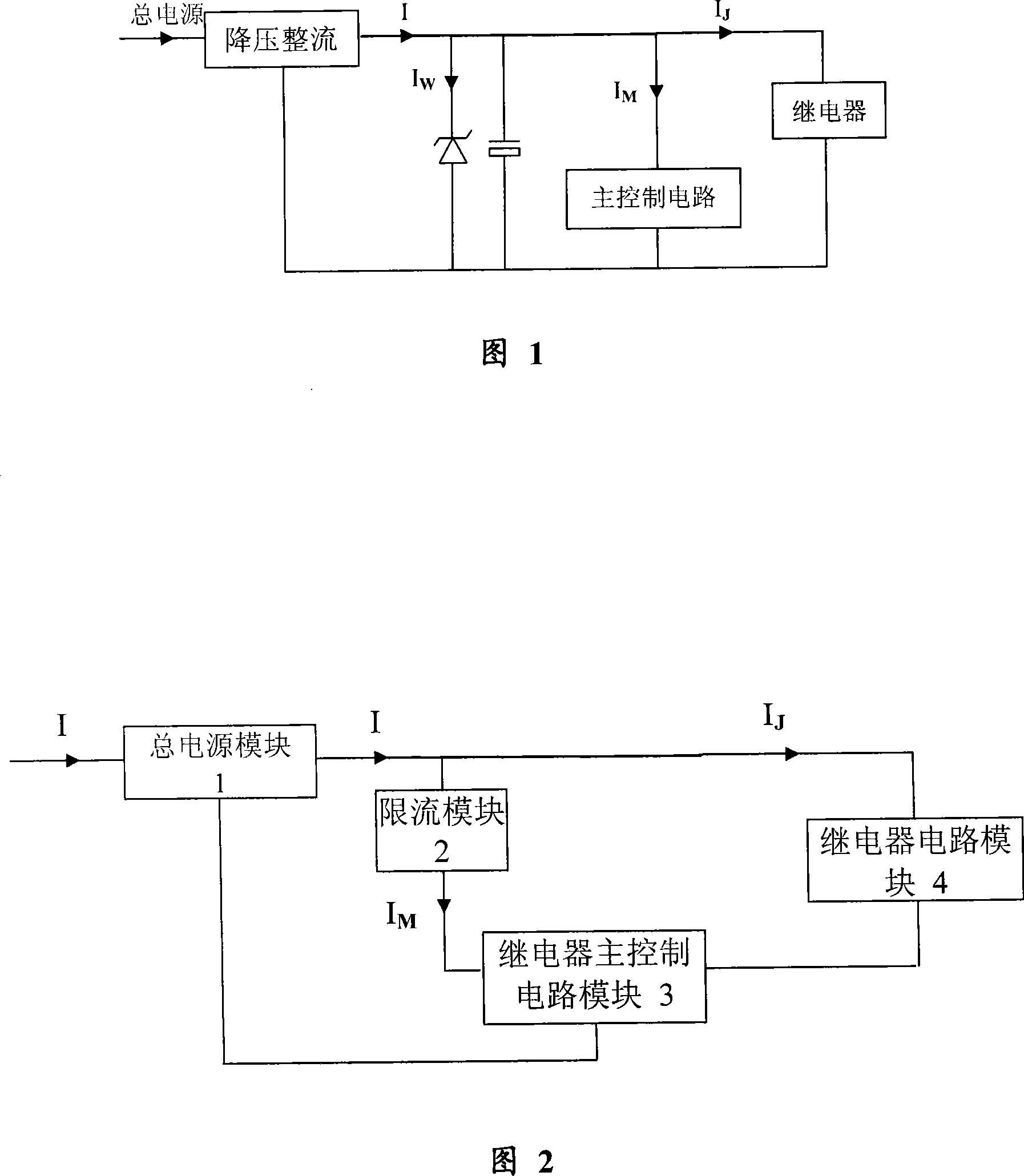
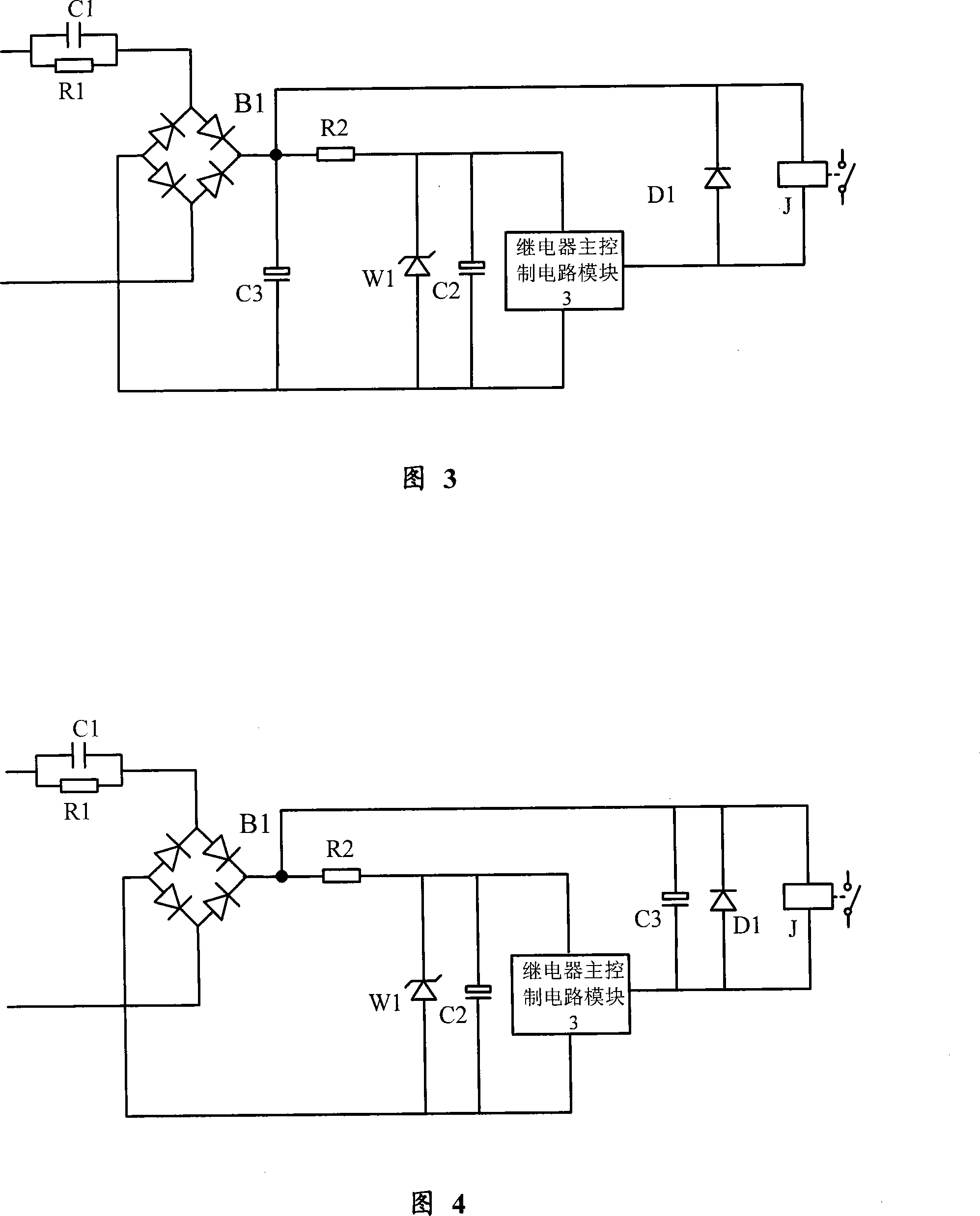
[0026] Please refer to FIG. 2, FIG. 3 and FIG. 4. The relay electrical control circuit device includes a main power supply module 1, a relay main control circuit module 3 and a relay circuit module 4 connected to the main power supply module 1. The described The relay main control circuit module 3 controls the working state of the relay circuit module 4, wherein the device further includes a current limiting module 2, and the current limiting module 2 is connected to the main power module 1 and the relay main control between circuit modules 3.

[0027] At the same time, the current limiting module 2 is a current limiting resistor R2, and the current limiting resistor R2 is connected in series between the main power module 1 and the relay main control circuit module 3; the current limiting module 2 may also include a first A...


PUM


Abstract

The invention relates to an electrical control circuit device for relays, which comprises a main power source module, a relay main control circuit module and a relay circuit module which are connected with the main power source module, wherein the relay main control circuit module controls the working condition of the relay circuit module. The device of the invention comprises a current limiting module which is connected between the main power source module and the relay main control circuit module. By employing the electrical control circuit device for relays, quiescent current only is current of the relay main control circuit module, and action current of the relay circuit module is not included, thereby greatly decreasing quiescent electrical power consumption. Current of most main control circuit modules, however, such as remote control reception, human induce and the like can be small, thereby effectively reducing quiescent current of the relay control circuit and saving energy consumption. The circuit structure is simple, the working properties are stable and reliable, and the applicability is wide, thereby laying a solid foundation for further popularization and application and energy saving of electrical control circuit.

Description

technical field [0001] The invention relates to the field of electronic circuits, in particular to the technical field of relay electronic control, in particular to a relay electrical control circuit device. Background technique [0002] In the current relay control circuit, generally the control circuit and the relay share a power supply. Regardless of whether the relay is closed or not, the circuit current is relatively large. Especially in the circuit using Zener diode, please refer to Figure 1, when the relay is not closed, the total current of the circuit I=I M +I W , where I M consumed by the main circuit, I W is the current flowing through the Zener diode, the total current I when the relay is closed / = I M / +I W / +I J . [0003] because I M ≈I M / , I W ≈I W / +I J , so I≈I / , that is, I and I before and after the relay pull-in / Basically equal, the actual result is that although the relay does not pull in at static state, the current consume...

Claims


Application Information

Patent Timeline
IPC IPC(8): H01H47/02
Inventor 朱晓军
Owner 西蒙电子商务(中国)有限公司
Why Eureka
Try Eureka