Single end driver transformer
A technology for transformers and flyback transformers, applied in the fields of transformer/inductor magnetic core, inductor/transformer/magnet manufacturing, electrical components, etc., can solve the problems of large size and high cost of flyback transformers, reduce residual magnetic induction, reduce Weight, the effect of reducing product cost
- Summary
- Abstract
- Description
- Claims
- Application Information
AI Technical Summary
Problems solved by technology
Method used
Image

Examples
Example Embodiment
[0031] Example 1
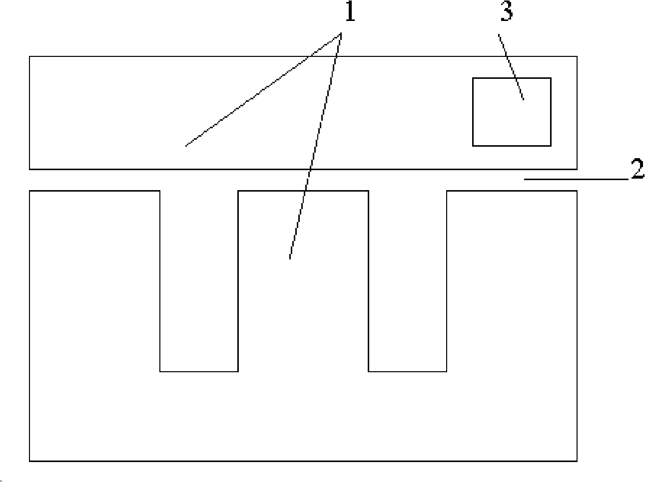
[0032] Such as figure 2 Shown is the output transformer magnetic core of the switching power supply, the magnetic core 1 is made of soft magnetic material, and the excitation method is single-ended reverse excitation. In this example, the shape of the magnetic core 1 is "EI" type, there are three air gaps 2 in the magnetic circuit, and the permanent magnets 3 are installed on both sides of the magnetic core 1 close to the air gap 2. In this example, a permanent magnet 3 is installed on one side of the magnetic core 1 and the air gap 2. According to the test, this installation method can achieve better results-under the same conditions (the initial permeability of the magnetic core μ 0 , Cross-sectional area S, transformer winding turns N, etc.) can obtain a larger magnetizing inductance L. The magnetic pole of the permanent magnet 3 should be selected so that the direction of the magnetic field in the magnetic core 1 is opposite to the direction of the magnetic...
Example Embodiment
[0033] Example 2
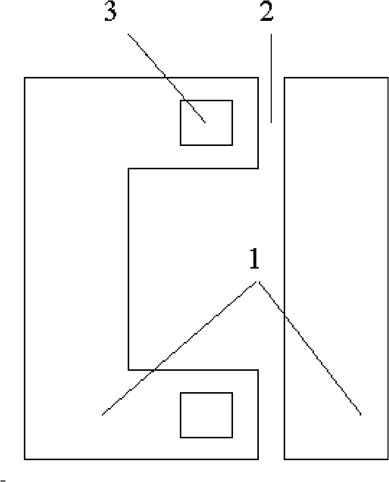
[0034] This example is a "UI" type magnetic core, such as image 3 Shown. The magnetic core has two air gaps 2. In this example, a permanent magnet 3 is installed in each of the two air gaps. The polarity of the two permanent magnets should be opposite to the direction of the magnetic field when the magnetic core 1 works.
Example Embodiment
[0035] Example 3
[0036] The transformer in this example is a flyback transformer with a core shape like Figure 4 Shown. The magnetic core of the flyback transformer has two air gaps. The transformer winding is mounted on one air gap 2 of the magnetic core 1, and the other air gap 2 is outside the winding. The permanent magnet 3 is pasted by the adhesive beside the air gap, such as Figure 5 Shown. Figure 5 The arrow 10 is the direction of the excitation magnetic field when the flyback transformer is working, and the arrow 30 is the direction of the magnetic field of the permanent magnet 3 in the core 1. The two permanent magnets in this example are installed on one side of the magnetic core 1 and on both sides of the air gap 2. The polarities of the two permanent magnets 2 are opposite, and the magnetic field generated by them is opposite to the magnetic field when the magnetic core 1 is working.
PUM
 Abstract
Description
Claims
Application Information
 - R&D Engineer
- R&D Manager
- IP Professional
- Industry Leading Data Capabilities
- Powerful AI technology
- Patent DNA Extraction
Browse by: Latest US Patents, China's latest patents, Technical Efficacy Thesaurus, Application Domain, Technology Topic.
© 2024 PatSnap. All rights reserved.Legal|Privacy policy|Modern Slavery Act Transparency Statement|Sitemap