Close range photography measuring device based on flat mirror and photogrammetric survey method

A technology of close-range photography and measurement devices, which is applied in photogrammetry/video measurement, measurement devices, camera devices, etc., to achieve the effects of improving work efficiency, ensuring measurement safety, and reducing the height of photography

Inactive Publication Date: 2008-09-10
HARBIN INST OF TECH
View PDF0 Cites 2 Cited by
  • Summary
  • Abstract
  • Description
  • Claims
  • Application Information

AI Technical Summary

Problems solved by technology

[0003] The purpose of the present invention is to solve the problem that it is difficult for the camera to directly look down on the object to be measured when the traditional close-range photogrammetry shoots the measured object with a relatively large size, and to provide a close-range photographic device and a photographic method based on a plane mirror

Method used


Image

  • Close range photography measuring device based on flat mirror and photogrammetric survey method
  • Close range photography measuring device based on flat mirror and photogrammetric survey method
  • Close range photography measuring device based on flat mirror and photogrammetric survey method

Examples


specific Embodiment approach 1

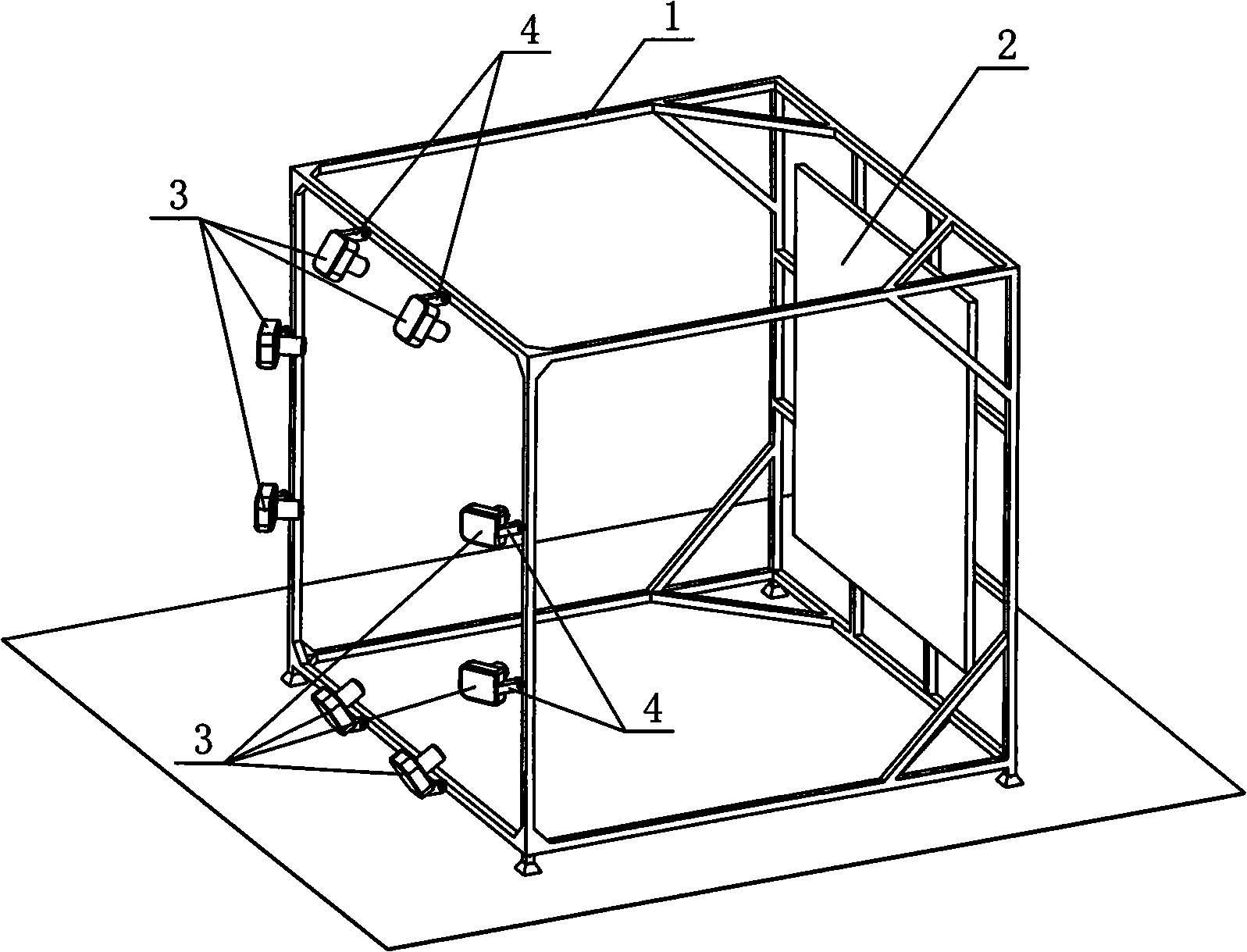
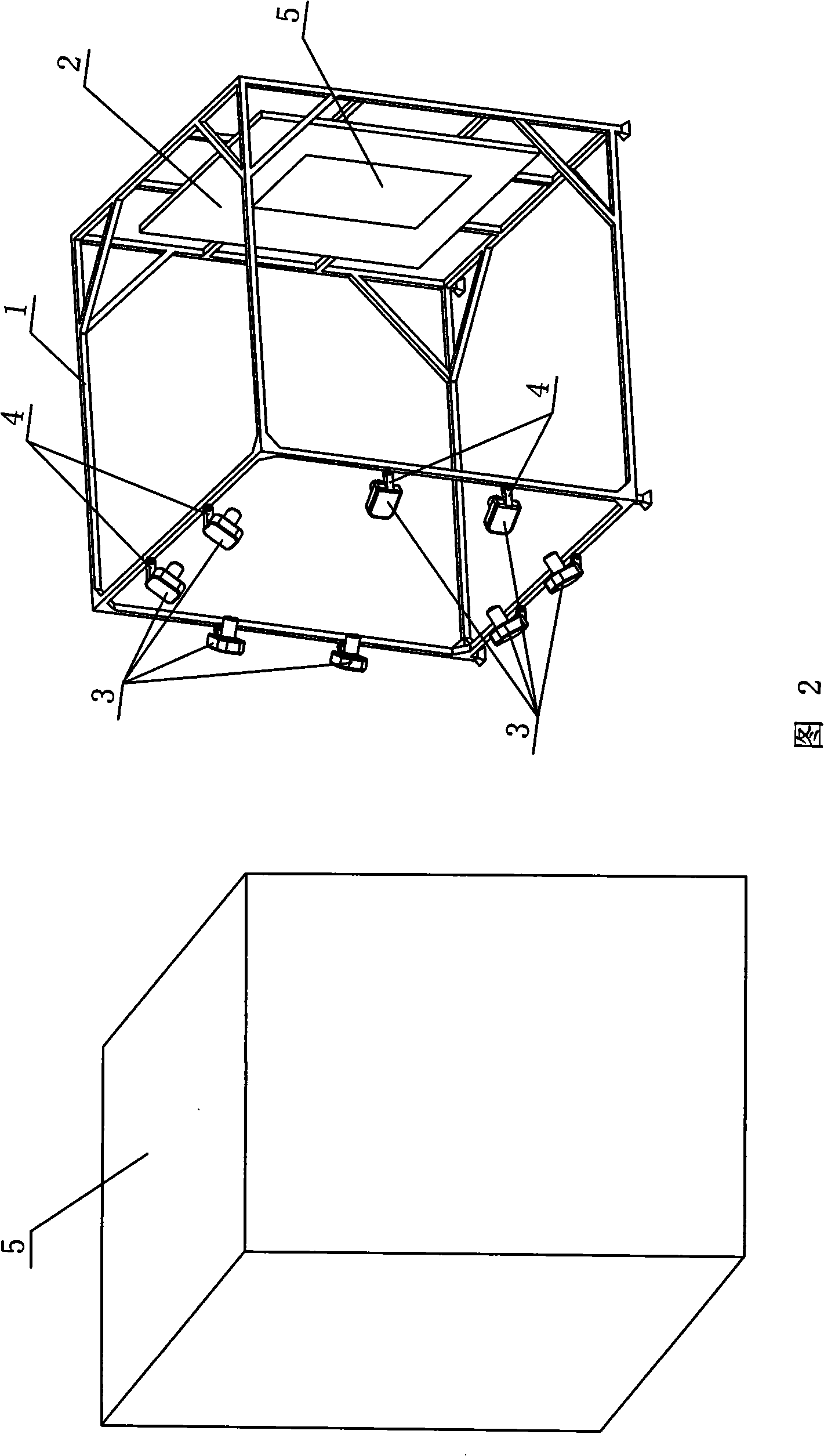
[0008] Specific implementation mode one: combine figure 1 Describe this embodiment, this embodiment comprises three-dimensional frame 1, plane mirror 2 and video camera 3, and plane mirror 2 is arranged on a face inside three-dimensional frame 1 and is perpendicular to the ground, camera 3 is arranged on three-dimensional frame 1 and is opposite to plane mirror 2 positions , the lens of the camera 3 is aimed at the plane mirror 2. The present invention combines the mirror imaging of the plane mirror 2 with close-range photogrammetry by means of a plane mirror 2. The function of the plane mirror 2 is equivalent to "shrinking" the size of the object to be photographed, thereby greatly simplifying the complexity of the measurement work. Therefore, the present invention is particularly It is suitable for shooting objects of huge size, or for photogrammetry of large objects in limited indoor space.

specific Embodiment approach 2

[0009] Specific implementation mode two: combination figure 1 Describe this embodiment, the difference between this embodiment and the first embodiment is that it also adds a rotation adjustment device 4, one end of the rotation adjustment device 4 is connected with the camera 3, and the other end of the rotation adjustment device 4 is hinged on the three-dimensional frame 1 . This design can make the camera 3 adjust the angle on the stereoscopic frame 1 so as to capture a suitable shooting angle.

specific Embodiment approach 3

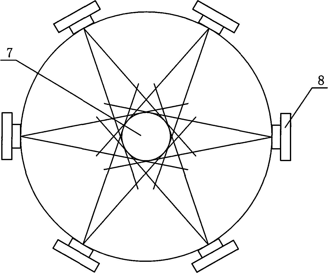
[0010] Specific implementation mode three: combination figure 1 This embodiment will be described. In this embodiment, the number of cameras 3 disposed on the three-dimensional frame 1 and opposite to the plane mirror 2 is 4-8. The number of cameras 3 within this range can increase the number of photographs collected and make the measurement results more accurate.


PUM


Abstract

The invention relates to a photography measurement device and a method, in particular to a close-range photography measurement device and a photography measurement method based on a plane mirror, which aim at solving the problem that a camera which is used for directly photographing and measuring the object to be measured in traditional close-range photography measurement can not directly photograph and measure the object to be measured when the object to be measured is comparatively high and big. The photography measurement device consists of a plane mirror which is arranged on one surface at the internal side of a solid frame and is vertical to the ground surface and a camera which is arranged on the solid frame and is opposite to the plane mirror. The photography measurement method is characterized in that the solid frame is moved to a position suitable for the object to be measured, the object to be measured is imaged in the plane mirror, the angle of each camera is adjusted to photograph the virtual image inside the plane mirror, the photo is then processed by photography measurement processing software, and the solid geometrical model of the object to be measured is finally obtained. The photography measurement device photographs the virtual image of the object to be measured inside the plane mirror. The requirement on the photography space height can be reduced when the photography measurement device and the photography measurement method are adopted for the photography and measurement of objects with large structure.

Description

technical field [0001] The invention relates to a photogrammetry device and method. Background technique [0002] Traditional close-range photogrammetry uses a camera to directly shoot and measure the measured object 7, that is, the lens 8 shoots at the measured object 7, and usually makes the camera look down and look up at different positions to shoot the object, see image 3 and Figure 4 , in this case, the height of the camera is usually higher than or at least close to the height of the measured object. However, in actual situations, if the object to be measured is high and the height of the measurement space accommodating the object is not enough to meet the conditions of overlooking the shooting, it is difficult to complete this kind of shooting; The method of erecting a camera in a high space is not only complicated to operate, but also has high measurement costs, and there is a certain risk of personal injury in the measurement. Contents of the invention [000...

Claims


Application Information

Patent Timeline
IPC IPC(8): G01C11/00G01C11/02
Inventor 林国昌谭惠丰王友善谢志民苗常青王长国
Owner HARBIN INST OF TECH
Why Eureka
Try Eureka