Automatic break injection mold when side runner fuses
A technology of automatic cutting and side gate, which is applied in the field of plastic injection molds, can solve the problem of easy scars on the shear gate, achieve the effect of highlighting substantive features, reducing labor intensity and improving production efficiency
- Summary
- Abstract
- Description
- Claims
- Application Information
AI Technical Summary
Problems solved by technology
Method used
Image

Examples
Example Embodiment
[0050] Example 1
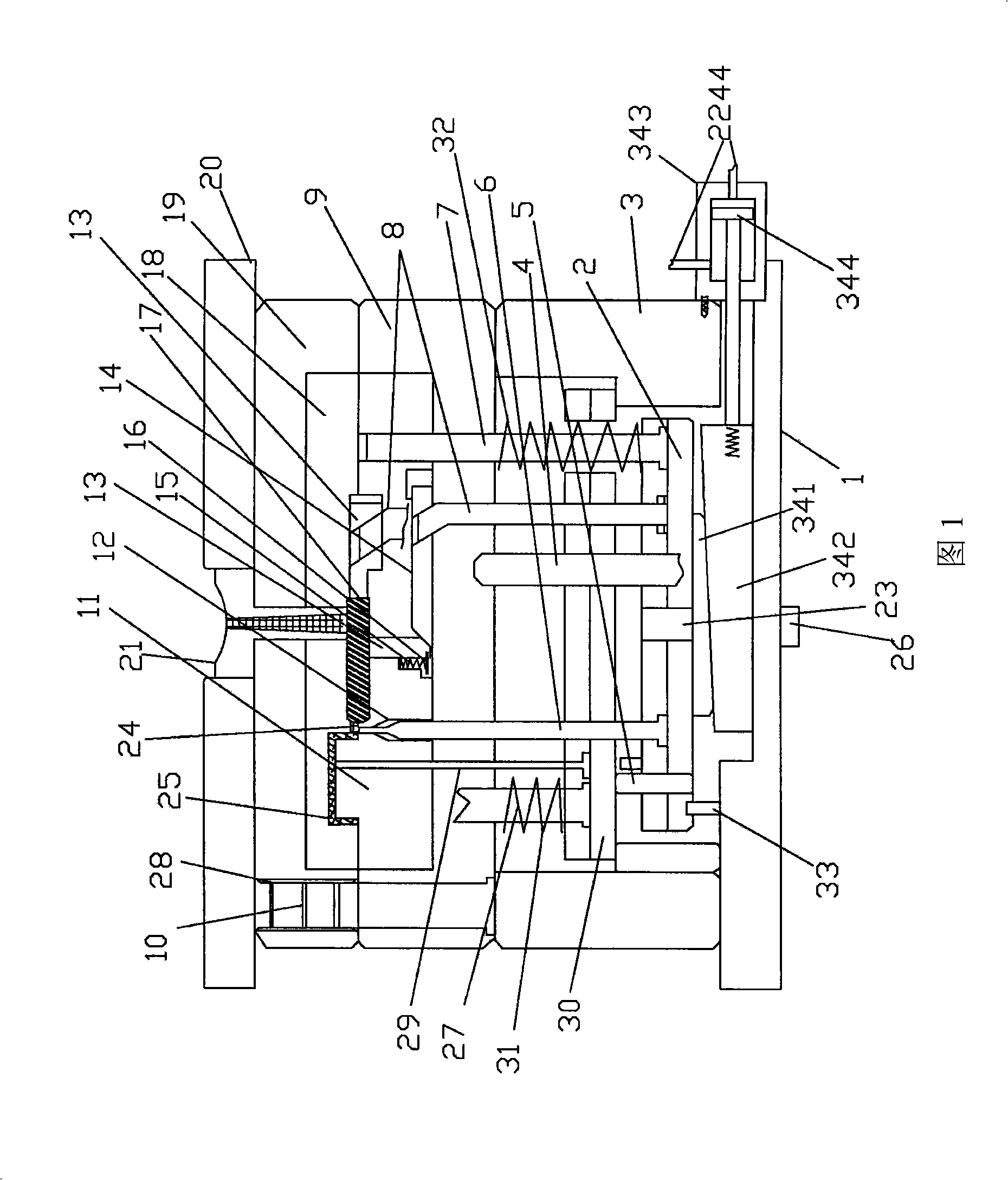
[0051] Refer to Figure 1, when the side gate is melted, the injection mold is automatically cut off, including the movable mold bottom plate 1, two mold feet 3, cavity B plate 9, cavity A plate 19, fixed mold bottom plate 20, gate sleeve 21, and female mold Insert 18, male mold insert 11, large guide post 10, large guide sleeve 28, discharge plate 30, discharge plate reset rod 27, discharge plate return spring 31, ejector rod 29, and small guide column 4.
[0052] The two mold feet 3 are fixedly installed on both sides of the movable mold bottom plate 1 by fasteners, and the cavity B plate 9 is also fixedly installed on the two mold feet 3 by fasteners; a number of mold feet 3 are installed on the cavity B plate 9 Large guide post 10. The cavity A plate 19 is installed on the fixed mold bottom plate 20 by fasteners, the large guide sleeve 28 is installed in the cavity A plate 19, the large guide post 10 is inserted into the large guide sleeve 28, and the two are...
Example Embodiment
[0064] Example 2
[0065] See Figure 8 and Figure 9, Picture 10 The difference between Embodiment 2 and Embodiment 1 is that the pushing mechanism is different, and the rest are the same. The pushing mechanism of this embodiment includes a mounting plate 221 installed on the bottom plate 1 of the movable mold. The mounting plate 221 is provided with a bearing 224. The two ends of the camshaft 222 are respectively installed in the bearing 224, and each camshaft 222 is mounted with an eccentric Cam 223, a stepping motor 225 is installed on a mounting plate 22, a driving sprocket 226 is sleeved on the output shaft of the stepping motor 225, and a driven sprocket 227 is installed at the end of each camshaft 222 A synchronization chain 228 surrounds the driving sprocket 226 and the driven sprocket 227. The stepping motor 225 is connected with and controlled by the computer console of the injection machine.
[0066] When the mold is closed and filled and the pressure-holding plastic is...
Example Embodiment
[0068] Example 3
[0069] See Picture 11 with Picture 12 The difference between the third embodiment and the second embodiment is that the stepping motor 221 in the pushing mechanism is replaced by an oil cylinder 343 and a rack 345, and the rest is the same as the first embodiment. The pushing mechanism of this embodiment includes a mounting plate 221 mounted on the bottom plate 1 of the movable mold. Both ends of the camshaft 222 are provided on two mounting plates 22 through bearings 224. An eccentric cam 223 is mounted on each camshaft 222. A driven sprocket 227 is installed at the shaft end of each camshaft 222, and a synchronization chain 228 is surrounded by the two driven sprocket 227. A gear 346 is installed on the shaft end of a camshaft 222, an oil cylinder 343 is installed on a mounting plate 221, and a rack 345 is installed on the piston 344 of the oil cylinder 343, and the rack 345 meshes with the gear 346. The oil cylinder 343 is supplied with oil by an oil pump c...
PUM
 Abstract
Description
Claims
Application Information
 - R&D Engineer
- R&D Manager
- IP Professional
- Industry Leading Data Capabilities
- Powerful AI technology
- Patent DNA Extraction
Browse by: Latest US Patents, China's latest patents, Technical Efficacy Thesaurus, Application Domain, Technology Topic.
© 2024 PatSnap. All rights reserved.Legal|Privacy policy|Modern Slavery Act Transparency Statement|Sitemap