Supercharge Your Innovation With Domain-Expert AI Agents!

Dropper for strong corrosive chemical agent and use method thereof

A chemical reagent, corrosive technology, applied in the structural field of chemical reagent tip dropper, can solve the problems of corrosion, tip chemical damage and so on

Inactive Publication Date: 2008-11-19
周巽
View PDF0 Cites 1 Cited by
  • Summary
  • Abstract
  • Description
  • Claims
  • Application Information

AI Technical Summary

Problems solved by technology

——Solve the problem of chemical damage (corrosion) of the above-mentioned corrosive chemical reagents to the tip

Method used


Image

  • Dropper for strong corrosive chemical agent and use method thereof
  • Dropper for strong corrosive chemical agent and use method thereof

Examples


Embodiment Construction

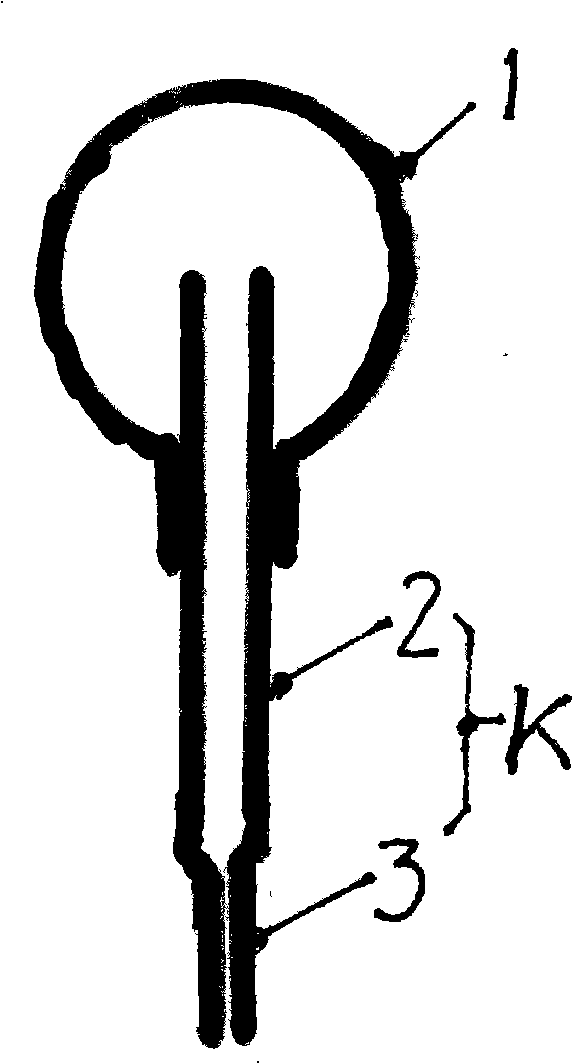
[0021] As shown in Figure 1:

[0022] It is not difficult to find out that the dropper in the suction tip dropper of the prior art product is composed of a single-head dropper K, and the rear portion (top) of the single-head dropper K is completely open in the cavity of the suction head 1. , as long as the drip chamber 2 constituting the single-head dropper K still has unused residual chemical preparations, there is a possibility that the residual chemical preparations will flow back into the cavity of the suction head 1 . ——Because, under normal circumstances, the user of the tip dropper will temporarily tilt the drop hole of the tip dropper upwards or place it horizontally for various reasons during the interval of continuous work Or for a period of time, like this, it is unavoidable that the possibility of allowing the above-mentioned residual chemical preparation to flow back from the drip chamber 2 into the cavity of the suction head 1 will inevitably occur, and this poss...


PUM


Abstract

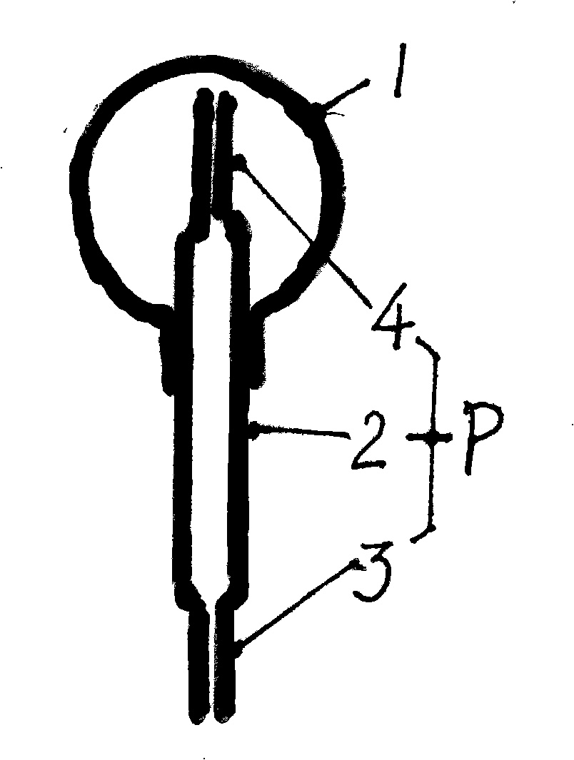
The invention relates to a sucker dropper used for strong corrosive chemical agents and the application methods thereof. The sucker dropper structurally comprises a sucker (1) (which is made of normal rubber or rubber plastic) and a single head dropper (k) matched with the sucker, and is characterized in that the single head dropper (k) is replaced by a double head dropper (p). The sucker dropper creates conditions for preventing the chemical damage to the sucker dropper caused by the chemical agent which is not used up once and remained in a dropper cavity (2) entering into the cavity of the sucker (1) during the operation process (such as the chemical corrosion of strong base agent to the rubber or the rubber plastic). According to the matching method of the dropper cavity (2) and a second dripper (4), the two application methods of 'controlled and limited sucking' of chemical agent and 'non controlled and limited sucking' of chemical agent can be formed. When an operator freely and momentarily makes the sucker dropper in the prior art be inclined upward or horizontally laid (the phenomena frequently happens during work), the non exhausted chemical agent can easily flow into the cavity of the sucker (1) to cause the chemical damage (corrosion) to the sucker (1).

Description

technical field [0001] The present invention relates to the structural technology of chemical reagent dropper and its use method, especially can prevent corrosive chemical reagent from entering in the rubber or rubber-plastic suction head cavity that constitutes suction-head dropper (prevent rubber or rubber-plastic suction head from being damaged. Loss) structural techniques and methods of use. Background technique [0002] At present, it involves chemical and pharmaceutical industries such as the tip dropper used in the laboratory. After the tip dropper has inhaled a corrosive chemical reagent (for example: sodium hydroxide reagent), once it is not removed during use When it is used up, usually the outlet hole of the dropper of the tip is temporarily tilted up or placed horizontally, and the reagent remaining in the single-head dropper is likely to flow back from its fully open top into the liquid that is mainly made of rubber or In the cavity of the tip made of rubber an...

Claims


Application Information

Patent Timeline
IPC IPC(8): B01L3/02
Inventor 周巽
Owner 周巽
Features
  • R&D
  • Intellectual Property
  • Life Sciences
  • Materials
  • Tech Scout
  • Unparalleled Data Quality
  • Higher Quality Content
  • 60% Fewer Hallucinations
Learn More