Supercharge Your Innovation With Domain-Expert AI Agents!

Technique for shaping a ribbon-shaped ion beam

An ion beam and ribbon technology, applied in the technical field of ribbon ion beam shaping

Active Publication Date: 2012-02-29
VARIAN SEMICON EQUIP ASSOC INC
View PDF2 Cites 0 Cited by
  • Summary
  • Abstract
  • Description
  • Claims
  • Application Information

AI Technical Summary

Problems solved by technology

In addition, a specific shape of electrodes can only be used for adjustment of a specific beam shape or supply of ion beams

Method used


Image

  • Technique for shaping a ribbon-shaped ion beam
  • Technique for shaping a ribbon-shaped ion beam
  • Technique for shaping a ribbon-shaped ion beam

Examples


Embodiment Construction

[0131] Embodiments of the present application illustrate improved electrostatic lenses having one or more segmented suppression electrodes. These electrodes may comprise segments that are independently or individually biased relative to each other, thereby providing flexible and efficient manipulation of the ion beam shape as well as its energy.

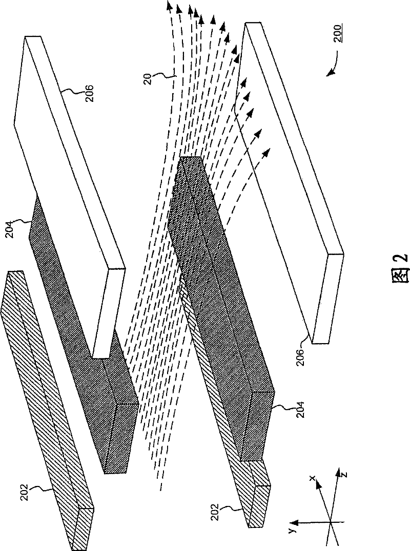
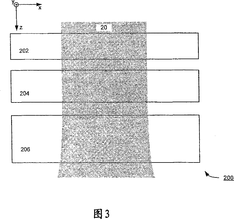
[0132] see Figure 4 , which shows a perspective view of an electrostatic lens 400 according to an embodiment of the application. Somewhat similar to the conventional electrostatic triode lens, the electrostatic lens 400 may include an entrance electrode 402 and an exit electrode 406 . However, rather than a single suppression electrode, electrostatic lens 400 may include multiple electrodes (collectively "suppression electrodes 404") between entrance electrode 402 and exit electrode 406. In other words, a typically single suppression electrode can be segmented into multiple electrodes (or segments) that can be independently positi...


PUM


Abstract

A technique for shaping a ribbon-shaped ion beam is disclosed. In one particular exemplary embodiment, the technique may be realized as an apparatus for shaping a ribbon-shaped ion beam. The apparatus may comprise an electrostatic lens having a substantially rectangular aperture for a ribbon-shaped ion beam to pass through, wherein a plurality of focusing elements are positioned along short edgesof the aperture, and wherein each focusing element is separately biased and oriented to shape the ribbon-shaped ion beam.

Description

technical field [0001] This application relates to ion implantation, and more specifically, this application relates to ribbon ion beam shaping techniques. Background technique [0002] Ion implanters are widely used in semiconductor manufacturing to selectively alter the conductivity of materials. In a typical ion implanter, ions generated from an ion source are directed through a series of beamline assemblies including one or more analyzing magnets and a plurality of electrodes. The analysis magnet selects the desired ion species, filters out contaminant species and ions with incorrect energies, and also adjusts the ion beam quality at the target wafer. Properly shaped electrodes can be used to modify the energy as well as the shape of the ion beam. [0003] figure 1 A known ion implanter 100 is shown comprising an ion source 102, an extraction electrode 104, a 90° magnet analyzer 106, a first deceleration (D1) stage 108, a 70° magnet analyzer 110, and a second decelera...

Claims


Application Information

Patent Timeline
Patent Type & Authority Patents(China)
IPC IPC(8): H01J37/12H01J37/30H01J37/317
Inventor 史费特那·B·瑞都凡诺彼德·L·凯勒曼维克多·M·本夫尼斯特罗伯特·C·林德柏格肯尼士·H·波什泰勒·B·洛克威尔詹姆士·史帝夫·贝福安东尼·雷诺
Owner VARIAN SEMICON EQUIP ASSOC INC
Features
  • R&D
  • Intellectual Property
  • Life Sciences
  • Materials
  • Tech Scout
  • Unparalleled Data Quality
  • Higher Quality Content
  • 60% Fewer Hallucinations
Learn More