
Binding management apparatus, method and product

A binding management and binding technology, applied in the direction of electrical digital data processing, special data processing applications, instruments, etc., can solve problems such as difficult modification, complexity, and wiring that cannot be placed

Inactive Publication Date: 2009-03-04
FUJITSU LTD
View PDF6 Cites 2 Cited by
  • Summary
  • Abstract
  • Description
  • Claims
  • Application Information

AI Technical Summary

Problems solved by technology

This is because other wires cannot be placed along the route of the base wire
However, it is not clear at the design stage of route determination which route is the longest route for common use, so care must be taken during manufacturing, and this is not easily modifiable
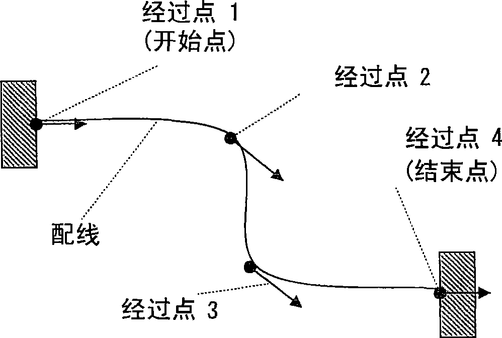
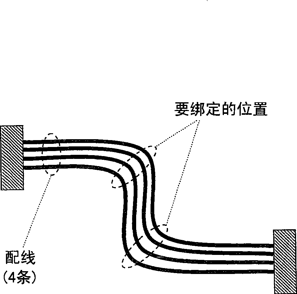
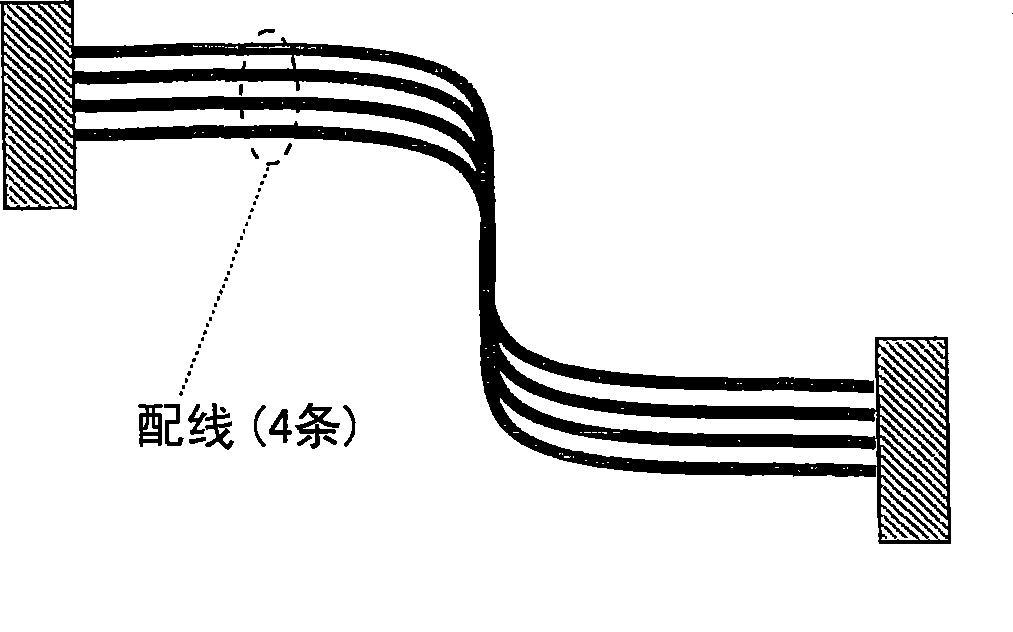
[0015] When expecting a configuration such as Image 6 As shown in the equally complex wiring, as Image 6 As shown in 3801 and 3802 in , it is necessary to set multiple reference wirings, and complex operations are required
[0016] Also, in the method of determining a wiring as a reference and placing other multiple wirings along it, such as Figure 5 As shown in , since only one route is set and the necessary wiring is generated along the reference, the process of generating only one route becomes necessary and its operation becomes cumbersome
[0017] Although techniques for co-routing and binding cables are disclosed, none of the above patent documents 1-3 disclose techniques for shaping and displaying soft objects based on binding routes.

Method used


Image

  • Binding management apparatus, method and product
  • Binding management apparatus, method and product
  • Binding management apparatus, method and product

Examples


Embodiment Construction

[0082] Preferred embodiments for realizing the present invention are described in detail below with reference to the accompanying drawings.

[0083] Figure 7 The configuration of a preferred embodiment of the wiring design support device according to the present invention is shown.

[0084]

[0085] Figure 7 The design support device 101 of this preferred embodiment shown in includes: a wiring management unit 102, a three-dimensional model management unit 103, a passing point management unit 104, a binding point management unit 105, a binding section management unit 106 , a binding route management unit 107 , a shape forming unit 108 and a display unit 109 .

[0086] Based on user input from the input device 110, the wiring management unit 102 edits and manages information related to routing of each wiring.

[0087] The three-dimensional model management unit 103 manages model data of components provided on a device to be designed (three-dimensional model data of compon...


PUM


Abstract

In the binding management apparatus, the passing point management unit stores the attribute of each passing point of harness and the like in a virtual design space in a passing point table as passing point information and manages it. The binding point management unit stores the attribute of a binding point obtained by binding each passing point of harness as binding point information including relationship information of the binding point of each passing point and independent of each piece of passing point information. The management unit collectively edits / displays bound harness and so on by editing the binding point information of the binding point table and reflecting the edition result in the passing point information related to the binding point information based on the relationship information.

Description

technical field [0001] The present invention relates to a system for designing / verifying equipment in a virtual space, and more particularly, to a design support technology for flexible linear and ribbon-like objects such as harnesses, metal cables, optical cables, and the like. Background technique [0002] Recently, three-dimensional data for device design has gradually increased, and a project verification method of verifying by generating prototypes in a design stage using product data in a virtual space realizes development of products in a short time. [0003] Electronic components arranged inside an electronic device, between an electronic device and another device, inside a building, etc. are electrically or optically connected to each other by wire harnesses, metal cables, optical cables, and the like. In such connection wiring of electric signals / optical signals such as wiring, cables, etc., the need for pre-verification at the design stage has increased. [0004]...

Claims


Application Information

Patent Timeline
IPC IPC(8): G06F17/50
CPCH02G3/28
Inventor 出水宏治木寺雅如
Owner FUJITSU LTD
Learn More