Unlock instant, AI-driven research and patent intelligence for your innovation.

Automatic multiple-focus focusing device and method thereof

A multi-focus, automatic technology, applied in the direction of installation, optics, instruments, etc., can solve the problems of correct focus position, inflexibility, and non-replacement, etc., and achieve the effect of improving productivity and design flexibility

Active Publication Date: 2010-10-13
DE&T
View PDF5 Cites 0 Cited by
  • Summary
  • Abstract
  • Description
  • Claims
  • Application Information

AI Technical Summary

Problems solved by technology

[0005] Therefore, when actually performing multi-focus focusing using an existing optical system, since the WD is determined by the optical system, there is no flexibility, and it is necessary to use multiple systems in terms of characteristics, and there is a large gap due to the flatness error of the instrument between the lenses. It is difficult to make the focus position exactly the same, and there is a disadvantage that the general telecentric lens cannot be used and only 100% custom-made (Order Made) design products must be used
[0006] In addition, due to the increase in the size of flat panel displays in recent years, it is required to install a precise focusing system in the system using the detector. From the perspective of problems in the inspection system caused by the increase in size, it is difficult to replace the detector due to size and model changes. Module (Probe Block), the number of detection modules due to the large size increases rapidly, and the replacement parts of the equipment become heavy due to the increase in size, so it cannot be replaced according to the size, and it is difficult to use the multi-focus using the existing optical system Focusing system to cope with inspection system problems caused by the enlargement of such flat panel displays

Method used


Image

  • Automatic multiple-focus focusing device and method thereof
  • Automatic multiple-focus focusing device and method thereof
  • Automatic multiple-focus focusing device and method thereof

Examples


Embodiment Construction

[0030]Preferred embodiments of the present invention will be described in detail below with reference to the accompanying drawings. When describing the present invention, if it is considered that the specific description of related known functions or configurations will unnecessarily obscure the gist of the present invention, the specific descriptions of these known functions or configurations will be omitted.

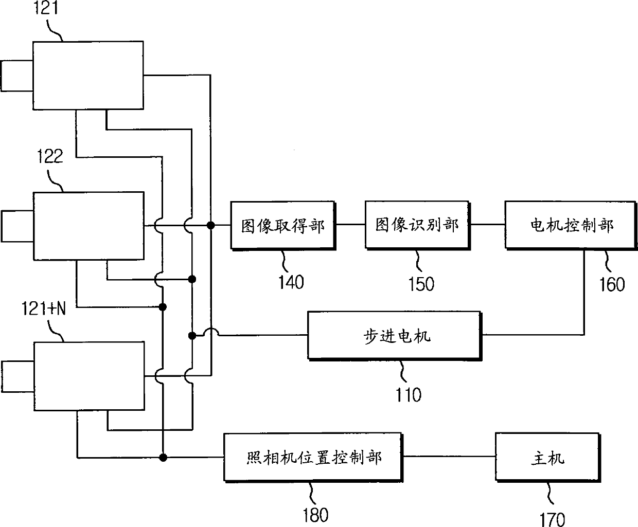
[0031] figure 1 is a schematic configuration diagram of the first embodiment of the automatic multi-focus focusing device of the present invention, figure 2 It is a detailed structural diagram of the first embodiment of the automatic multi-focus focusing device.

[0032] Here, reference numerals 121, 122, and 121+N represent a plurality of CCD cameras, that is, a CCD camera that captures a white and black (W / B: White and Black) focusing image covering an omnidirectional field of view (FOV) of the focusing mark. A focus camera, reference numeral 170 represents a host...


PUM


Abstract

The invention provides an automatic multi-focus focusing device capable of precision focusing in a large scale flat panel display system using a detector and a method thereof. The focusing device comprises a plurality of CCD cameras for shooting images for focusing use; a host camera which has position information corresponding to the CCD cameras and automatically controls the position and the focus height of a focusing camera based on action change and procedure change; a camera position control part which causes the CCD cameras to move based on the camera position information provided by the host camera; an image obtaining part which obtains shot focusing images; an image recognition part which recognizes the focusing images extracted from the image obtaining part to obtain the focusingposition information; a motor control part which generates motor control signals based on the focusing position information; a precision motor which responds to the control signals and causes the CCDcameras to selectively move up and down to realize the precision focusing; a worktable control part which generates worktable control signals based on the recognized focusing position information; and an ultraprecision worktable which responds to the worktable control signals and causes the CCD cameras to selectively move left and right to complete the precision focusing.

Description

technical field [0001] The present invention relates to an automatic multi-focus align technology, in particular to an automatic multi-focus align technology that can accomplish precise focus alignment in a large flat panel display (FPD: Flat Panel Display) system using a probe. Multi-focus focusing device and method thereof. Background technique [0002] Generally, when a probe is used to measure a liquid crystal substrate, it is necessary to correctly align the position of the liquid crystal substrate so that the probes of the probe come into contact with the electrodes of the liquid crystal substrate correctly. [0003] Conventionally, in a focusing system of a multi-focus system, multi-focus alignment is performed by using a WD (Working Distance: working distance) conversion device and a CCD camera that change the focus position by changing the optical path. [0004] That is, changing the focal position by optically differenting the optical path (PASS) means that the WD...

Claims


Application Information

Patent Timeline
Patent Type & Authority Patents(China)
IPC IPC(8): G02B7/28G02F1/13
Inventor 宋旺奎
Owner DE&T