Supercharge Your Innovation With Domain-Expert AI Agents!

Bandgap reference circuits for providing accurate sub-1V voltages

A technology of circuits and resistors, applied in the field of reference circuits, can solve problems such as inability to meet high-accuracy application requirements, and achieve the effect of reducing changes

Inactive Publication Date: 2009-04-22
TAIWAN SEMICON MFG CO LTD
View PDF0 Cites 3 Cited by
  • Summary
  • Abstract
  • Description
  • Claims
  • Application Information

AI Technical Summary

Problems solved by technology

This cannot meet the needs of high accuracy applications

Method used


Image

  • Bandgap reference circuits for providing accurate sub-1V voltages
  • Bandgap reference circuits for providing accurate sub-1V voltages
  • Bandgap reference circuits for providing accurate sub-1V voltages

Examples


Embodiment Construction

[0018] The making and using of the presently preferred embodiments are discussed in detail below. It should be appreciated, however, that the present invention provides many applicable inventive concepts that can be embodied in many specific contexts. The specific embodiments discussed are merely illustrative of specific ways to make and use the invention, and do not limit the scope of the invention.

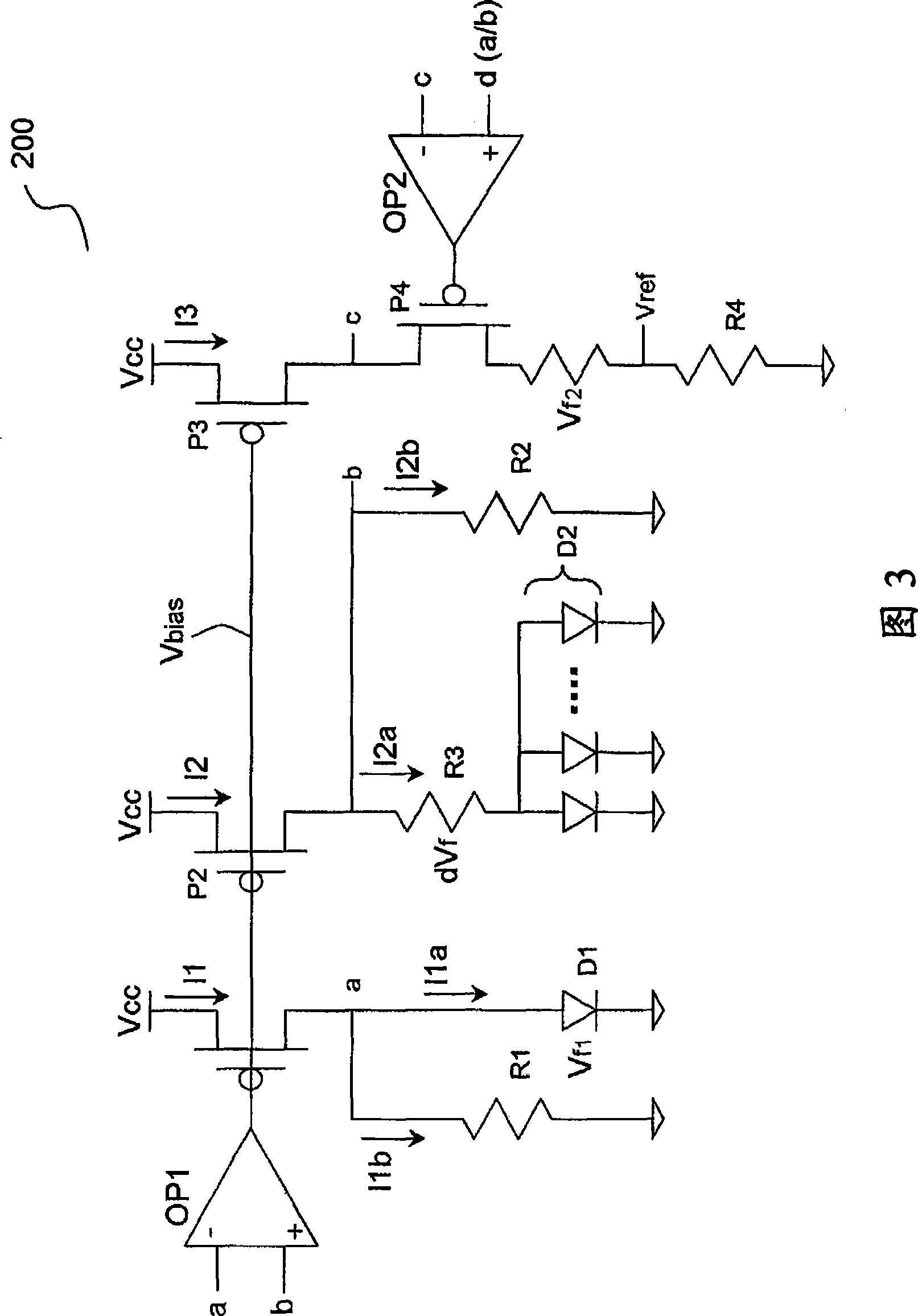
[0019] FIG. 3 illustrates a circuit diagram of a bandgap reference circuit 200, which includes PMOS devices P1, P2, and P3, the sources of which are connected to the supply voltage Vcc. The drain of the PMOS device P1 is connected to a resistor R1 and a diode D1, which are connected in parallel with each other. The drain of PMOS device P2 is connected to resistors R2 and R3, and resistor R3 is further connected in parallel to diode D2. Diodes D1 and D2 may be connected to ground. Nodes a and b of the drains of the PMOS devices P1 and P2 are also respectively connected to the ...


PUM


Abstract

A reference voltage circuit includes a first PMOS device having a first source, a first gate, and a first drain, wherein the first source is coupled to a power supply node; and a second PMOS device having a second source, a second gate and, a second drain. The second source is coupled to the power supply node. The first and the second PMOS devices have constant source-drain currents. The reference voltage circuit further includes a third PMOS device having a third source, a third gate, and a third drain; and a resistor coupled between the third drain and the ground. The third source is coupled to the power supply node. The first, the second, and the third gates are interconnected. The first, the second, and the third drains are virtually interconnected.

Description

technical field [0001] The present invention relates generally to a reference circuit, and in particular to a bandgap reference circuit capable of providing a sub-1 volt reference voltage. Background technique [0002] Bandgap reference circuits are widely used in analog circuits to provide stable, voltage-independent and temperature-independent reference voltages. In most precision analog chips, bandgap reference circuits are important. [0003] FIG. 1 illustrates a circuit diagram of a known bandgap reference circuit, which includes an operational amplifier 100 and a PMOS device 106 . The drain (drain) of PMOS device 106 is coupled to resistors 108 and 114 . Resistor 108 is coupled to ground via diode 112 . Resistor 114 is coupled to ground via resistor 118 and a plurality of diodes 120 . Operational amplifier 100 has inputs 102 and 104, which are connected to nodes 110 and 116, respectively. [0004] The reference voltage V122 at node 122 of the circuit shown in FIG....

Claims


Application Information

Patent Timeline
Patent Type & Authority Applications(China)
IPC IPC(8): G05F3/24
CPCG05F3/30
Inventor 赖逢时李嘉富王国铭薛旭峰
Owner TAIWAN SEMICON MFG CO LTD
Features
  • R&D
  • Intellectual Property
  • Life Sciences
  • Materials
  • Tech Scout
  • Unparalleled Data Quality
  • Higher Quality Content
  • 60% Fewer Hallucinations
Learn More