Method for measuring cofrequency multi-district observation time difference
A measurement method and multi-cell technology, applied in the field of TD-SCDMA communication, can solve problems such as poor results and inability to meet performance requirements
- Summary
- Abstract
- Description
- Claims
- Application Information
AI Technical Summary
Problems solved by technology
Method used
Image

Examples
Embodiment Construction
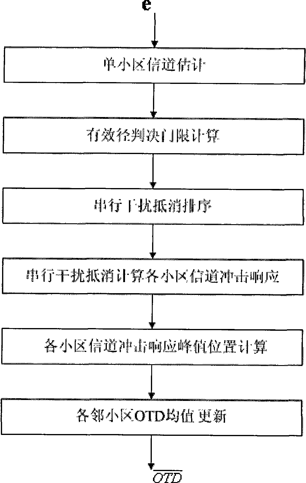
[0054] Such as figure 2 The present invention shown comprises 6 steps of implementation process, and its concrete steps are as follows:
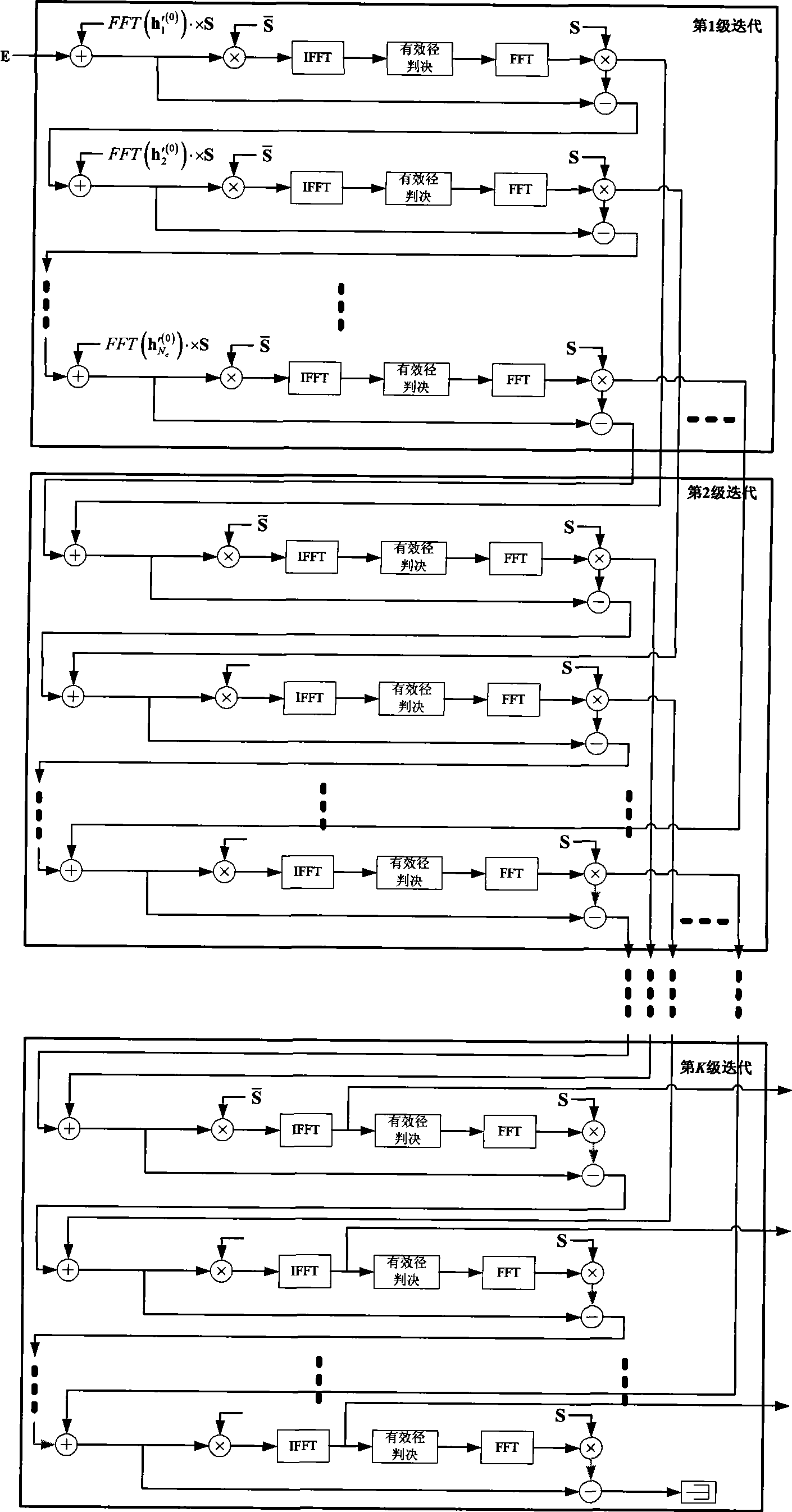
[0055] Suppose there are N c cells (including this cell), the downlink pilot sequence corresponding to each cell is si , i=1, 2,...N c In other words, first press the formula:
[0056] s ‾ = s ‾ ( 1 ) = s * ( 1 ) s ‾ ( i ) = ...
PUM
 Abstract
Description
Claims
Application Information
 - Generate Ideas
- Intellectual Property
- Life Sciences
- Materials
- Tech Scout
- Unparalleled Data Quality
- Higher Quality Content
- 60% Fewer Hallucinations
Browse by: Latest US Patents, China's latest patents, Technical Efficacy Thesaurus, Application Domain, Technology Topic, Popular Technical Reports.
© 2025 PatSnap. All rights reserved.Legal|Privacy policy|Modern Slavery Act Transparency Statement|Sitemap|About US| Contact US: help@patsnap.com