Check patentability & draft patents in minutes with Patsnap Eureka AI!

Pneumatic tire tread with sipes and mold blade

A tire tread, tread technology, applied in tire parts, tire tread/tread pattern, tire, etc., can solve problems such as rubber peeling

Inactive Publication Date: 2009-06-24
THE GOODYEAR TIRE & RUBBER CO
View PDF0 Cites 12 Cited by
  • Summary
  • Abstract
  • Description
  • Claims
  • Application Information

AI Technical Summary

Problems solved by technology

Also, depending on the shape of the groove, there may be rubber peeling at the intersection of the sipe and the groove

Method used


Image

  • Pneumatic tire tread with sipes and mold blade
  • Pneumatic tire tread with sipes and mold blade
  • Pneumatic tire tread with sipes and mold blade

Examples


Embodiment Construction

[0024] What is described below is what is presently believed to be the best mode of carrying out the invention. The description given here is intended to illustrate the general principles of the invention and should not be taken as limiting, the scope of the invention being best determined by reference to the appended claims.

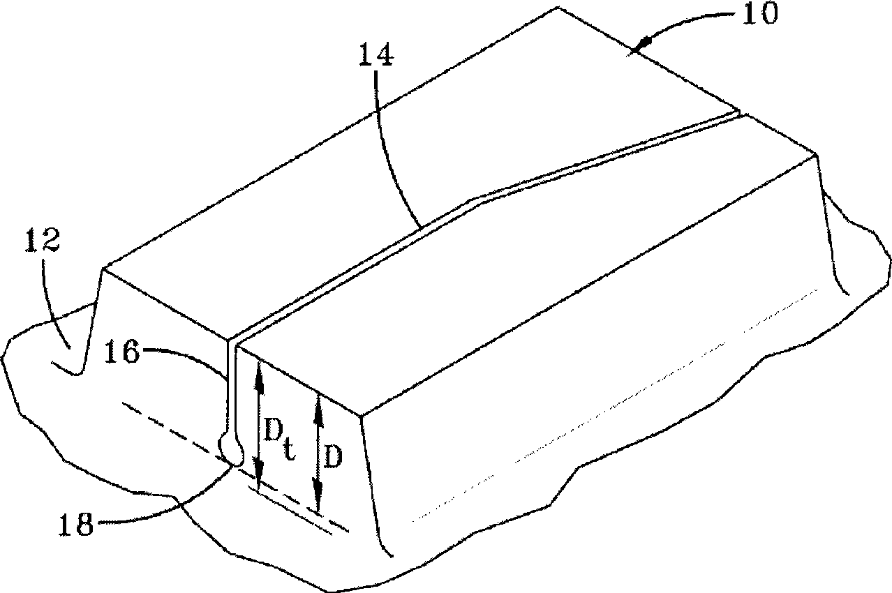
[0025] figure 1 is a tread element 10 for a pneumatic tire tread. As is well known to those skilled in the art, this tread element 10 is formed by at least one groove 12, either peripherally or laterally. If the tread element 10 were defined only by peripherally extending grooves, the tread element would be a tread rib. A tread element 10 is considered to be a tread block if it is formed by grooves on at least three sides. Tread elements 10 may be located anywhere on the tread, namely along the tread shoulders, along the centerline or some intermediate position. The depth of the grooves 12 forming the tread elements determines the antiskid depth Dt ...


PUM

PropertyMeasurementUnit
radiusaaaaaaaaaa
radiusaaaaaaaaaa

Abstract

The invention provides a tire tread, the tread having at least one circumferentially extending or laterally extending main groove, the maximum radial depth of the at least one main groove defining a non-skid tread depth, the at least one main groove partially forming at least one tread element, the at least one tread element having a sipe therein, wherein the sipe has a first portion and a second radiused portion, and a transition section located between the first portion and the second portion, the transition section having a curved surface with an outer radius that has a center external to the sipe, wherein the ratio of r1 / r2 ranges from about 0.1 mm to about 16 mm. The invention further includes a blade for molding a tire, the blade comprising a first portion and a second circular portion having a radius r2, and a curved transition section located between the first portion and the second portion, the transition section having an outer radius r1 that has a center external to the sipe, wherein the ratio of r1 / r2 ranges from about 0.3 mm to about 4 mm.

Description

[0001] This application claims the benefit of US Provisional Application No. 61 / 015466, filed December 20, 2007, the contents of which are incorporated by reference. technical field [0002] The present invention is directed to a pneumatic tire having a sipe. In particular, the present invention is directed to a tire tread in which the bottom of the sipe tread module is designed to provide significantly improved resistance to fatigue cracking. Background technique [0003] Tires generally use sipes on their treads in consideration of traction performance on wet roads. As the tread grooves increase in size and depth, fatigue cracks develop in the cover plate at the bottom of the sipe. This may be caused by fatigue due to repetitive cyclic loading due to braking torque. As the depth of the grooves increases, it becomes more difficult to remove the modules from the vulcanized tire without damaging the tire. In addition, depending on the shape of the groove, there may be rubb...

Claims


Application Information

Patent Timeline
Patent Type & Authority Applications(China)
IPC IPC(8): B60C11/03B60C11/117B60C11/13B29C33/42B29C35/02
CPCB60C2011/1213B29D2030/0613B60C11/12B29D30/0606B60C11/1281B60C11/1218
Inventor D·朔伊伦
Owner THE GOODYEAR TIRE & RUBBER CO
Features
  • R&D
  • Intellectual Property
  • Life Sciences
  • Materials
  • Tech Scout
  • Unparalleled Data Quality
  • Higher Quality Content
  • 60% Fewer Hallucinations
Learn More