Belt feeder

A feeder and chain belt technology, applied in the field of continuous feeding devices, can solve the problems that the bottom plate cannot withstand the warehouse pressure, the feeding is discontinuous, and the adjustment of the feeding amount is difficult, so as to prevent dust from flying, reduce pollution, and reduce vibration Effect

Inactive Publication Date: 2009-07-08
石建明
View PDF0 Cites 6 Cited by
  • Summary
  • Abstract
  • Description
  • Claims
  • Application Information

AI Technical Summary

Problems solved by technology

[0003] The disadvantages of the reciprocating feeder are: the bottom plate of the feeder needs to bear a large friction force of the material during the return journey, so a large driving power is required, and the energy consumption is large; due to the large power, the structural force is also large, and the weight of the equipment is large ;Because the feeding process is a reciprocating motion, the equipment vibrates greatly and the noise is also large; due to the large force on the structure, the moving parts wear quickly and the maintenance amount is large; due to the discontinuous feeding, the productivity is low
[0004] The disadvantages of the vibrating feeder are: due to the high frequency of feeding, the noise is also large; because it is fed by high-frequency vibration, its amplitude and frequency are greatly affected by the particle size and specific gravity of the material, so the feeding amount is unstable and the feeding It is also difficult to ad

Method used


Image

  • Belt feeder
  • Belt feeder
  • Belt feeder

Examples


Example Embodiment

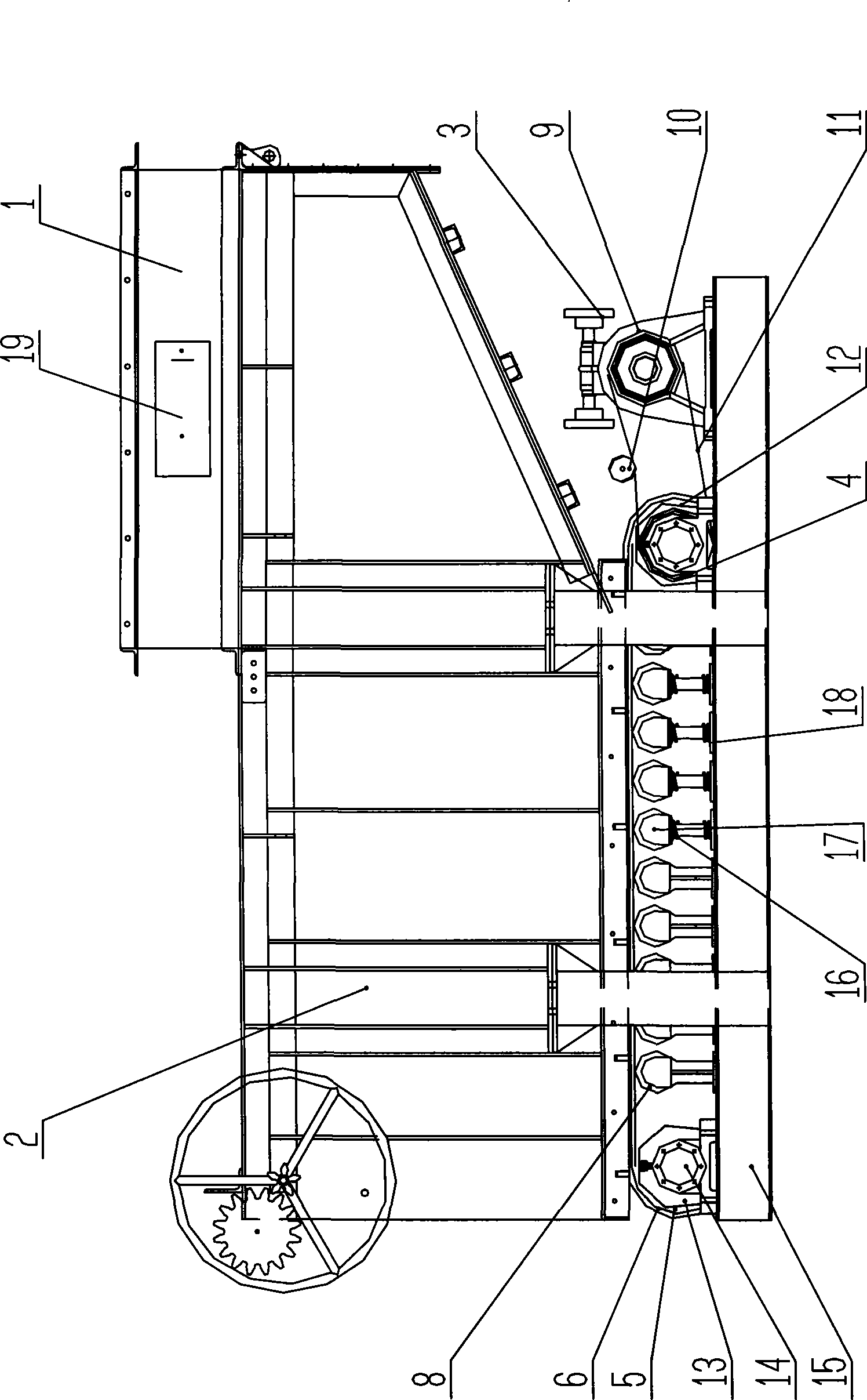
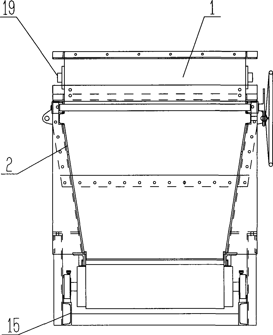
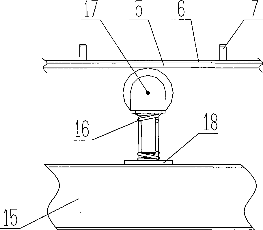
[0022] Such as Figure 1 to 2 As shown, in the belt feeder of the present invention, the feeding trough 1, the box body 2, the driving device 3 are installed on the base 15, and the driving drum 4 and the redirecting drum 13 are respectively installed on the base 15 through the bearing seat 14. , The bearing seat 14 is provided with an oil filling hole 20, which can be used to add oil and lubricate under the condition of continuous operation of the feeder. The support and the small drum 8 are installed on the base through the shock-absorbing support 17 and the shock-absorbing support bottom plate 18. 15. A chain belt consisting of a rubber-faced whole-core flame-retardant conveyor belt 5 and an armor belt 6. A raised plate 7 is evenly distributed on the armor belt 6, which can hang the material; the chain on the drive device 3. Wheel one 9 drives the sprocket two 12 on the drive drum 4 to rotate through the chain 11. A tension wheel 10 is installed on the chain 11 to adjust the tig...


PUM


Abstract

The invention relates to a belt type feeding machine, which comprises a feeding groove, a box body, a base, a driving device, a transmission roller, a turnabout roller, a supporting seat, a small roller and a chain belt. The belt type feeding machine is characterized in that the chain belt is formed by combining a rubber surface entire core inflaming retarding conveying belt and a shell belt, and the supporting seat and the small roller are arranged on the base through a damping spring to realize continuous feeding; materials and the chain belt have no relative movement in the feeding process, so the generated friction is small and running power is small; the feeding quantity in unit time can be conveniently regulated by regulating the rotating speed of a speed reducer or a frequency conversion motor; the damping spring is arranged among the supporting seat, the small roller and the base to reduce vibration furthest, reduce noise and improve the service life of parts; in addition, flying dust is difficult to generate, and the pollution can be reduced.

Description

technical field [0001] The invention relates to a mine equipment, in particular to a continuous feeding device. Background technique [0002] At present, the known feeders mainly include reciprocating feeders and vibrating feeders. The structure and working principle of the feeders of the two feeding methods are as follows: a material guide trough is set at the lower part of the silo, and the bottom plate of the material guide trough is movable. The type uses a power device to drive the bottom plate to move reciprocatingly. When the bottom plate moves towards the feeding port, the material moves together with the bottom plate to complete the feeding process; when the bottom plate moves in the opposite direction, the internal pressure and internal and external friction of the material Under the combined action, the materials do not move together with the bottom plate; the bottom plate keeps reciprocating, and the materials in the bin are continuously sent to the discharge por...

Claims


Application Information

Patent Timeline
IPC IPC(8): B65G65/42B65G15/30B65G23/08B65G69/18
Inventor 石建明
Owner 石建明
Why Eureka
Try Eureka