Supercharge Your Innovation With Domain-Expert AI Agents!

Control method and controller of steering lamp for motor vehicle

A control method and technology for turn signals, which are applied to vehicle components, optical signals, signaling devices, etc., can solve problems such as easy occurrence of traffic accidents, inability to implement steering instructions, and pedestrians and vehicles unable to know their intentions.

Inactive Publication Date: 2012-07-25
戴右铭
View PDF0 Cites 0 Cited by
  • Summary
  • Abstract
  • Description
  • Claims
  • Application Information

AI Technical Summary

Problems solved by technology

But when the emergency state switch is in the closed state and needs to send a turn signal, at this moment, the turn signal switch is closed, and the turn signal cannot be realized because the turn light indicator signals on both sides have been flashed in the emergency state indication mode at the same time, so that pedestrians and vehicles cannot know The driving intention of this car is prone to traffic accidents. At present, there are such hidden dangers in motor vehicles at home and abroad.

Method used


Image

  • Control method and controller of steering lamp for motor vehicle
  • Control method and controller of steering lamp for motor vehicle
  • Control method and controller of steering lamp for motor vehicle

Examples


Embodiment Construction

[0018] The above method and structure of the present invention can be further illustrated by the non-limiting examples given in the accompanying drawings.

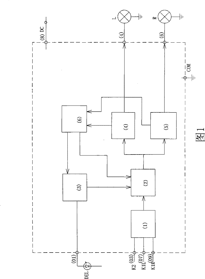
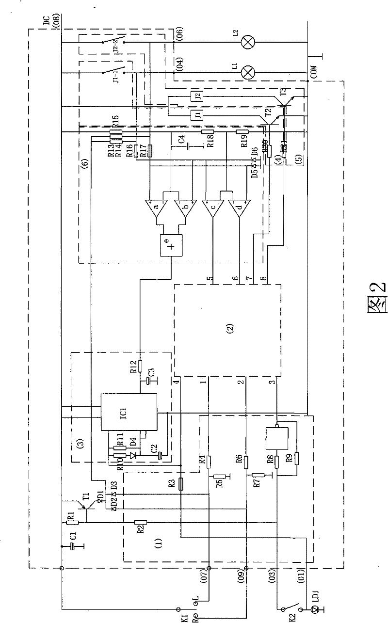
[0019] See attached figure 1 : The controller of the motor vehicle turn signal in the figure includes an input circuit 1 connected to the emergency light switch K2, left and right turn signal switches K1L and K1R respectively at the input end, a logical operation control module 2, output circuits 4 and 5, and pulse generation Circuit 3 and power supply 8, wherein the output end of the pulse generator is connected with the input end of the logic operation control module, after the input signal is processed by the input circuit 1, it is sent to the logic operation control module 2 together with the pulse signal of the pulse generator 3, the said The logic operation control module sends the result signal after analysis and processing to the output circuit to trigger the left and right turning lights; its feature is: the outpu...


PUM


Abstract

The invention relates to a method and a controller for performing steering indication in an emergency state by a steering lamp in the running of a motor vehicle. In the mode of an emergency state, a sThe invention relates to a method and a controller for performing steering indication in an emergency state by a steering lamp in the running of a motor vehicle. In the mode of an emergency state, a steering lamp switch is turned on, left and right steering lamps transmit different light indications. The steering lamps comprise the following control steps that when the steering lamp at the side toteering lamp switch is turned on, left and right steering lamps transmit different light indications. The steering lamps comprise the following control steps that when the steering lamp at the side to be steered flashes, the steering lamp at the other side is turned off, or when the steering lamp at the side to be steered flashes, the steering lamp at the other side is turned on all the time, or tbe steered flashes, the steering lamp at the other side is turned off, or when the steering lamp at the side to be steered flashes, the steering lamp at the other side is turned on all the time, or the flashing frequency of the lamp at the side to be steered is higher than that of the steering lamp at the other side. The steering lamps of a motor vehicle can more accurately indicate the running ihe flashing frequency of the lamp at the side to be steered is higher than that of the steering lamp at the other side. The steering lamps of a motor vehicle can more accurately indicate the running intend of the vehicle, particularly the running intend in the emergency lamp state, and thus, other running vehicles and pedestrians can be informed. The invention has the advantages of further enhancentend of the vehicle, particularly the running intend in the emergency lamp state, and thus, other running vehicles and pedestrians can be informed. The invention has the advantages of further enhancement of the running safety of motor vehicles and reduction of traffic accidents.ment of the running safety of motor vehicles and reduction of traffic accidents.

Description

technical field [0001] The invention relates to a control method and a controller of a motor vehicle driving intention state indicator light, in particular to a control method for the operation of the turn indicator light and the emergency state indicator light of the motor vehicle, so as to realize the correct display of the turn indication in the closed mode of the emergency state switch The invention discloses a novel control method and a controller for flashing lamps of motor vehicles. technical background [0002] In the prior art, the same group of light bulbs are used for the turn signals of the motor vehicle and the emergency state lights, which are controlled by the turn signal switch and the emergency state switch. The turn signal on the right side flashes to send a left or right turn flash signal; when an emergency signal needs to be sent, only when the emergency switch is closed, the left and right turn signals flash synchronously to send an emergency light signa...

Claims


Application Information

Patent Timeline
Patent Type & Authority Patents(China)
IPC IPC(8): B60Q1/34B60Q11/00
Inventor 戴右铭
Owner 戴右铭
Features
  • R&D
  • Intellectual Property
  • Life Sciences
  • Materials
  • Tech Scout
  • Unparalleled Data Quality
  • Higher Quality Content
  • 60% Fewer Hallucinations
Learn More