High-voltage energy-storage hydraulic work device

A working device and high-pressure energy storage technology, which is applied in the direction of fluid pressure actuators, servo motor components, mechanical equipment, etc., can solve the problems of endangering the safety of hydraulic turbine equipment, many pipe joints, and easy leakage, so as to facilitate installation and maintenance. The effect of stable system pressure and high reliability

Inactive Publication Date: 2009-09-16
福建省龙杰特电机有限责任公司
View PDF0 Cites 10 Cited by
  • Summary
  • Abstract
  • Description
  • Claims
  • Application Information

AI Technical Summary

Problems solved by technology

[0002] The existing water turbine inlet valve control system in China still adopts the structure of the air-supplementing oil pressure device. For decades, the cast stop valve has been used as the control element in the control system, and all of them are connected by steel pipelines. Therefore, the control The layout of the components is relatively scattered, resulting in a large volume of the control device, inconvenient operation,

Method used


Image

  • High-voltage energy-storage hydraulic work device

Examples


Example Embodiment

[0007] The embodiments of the present invention will be further described below with reference to the accompanying drawings.

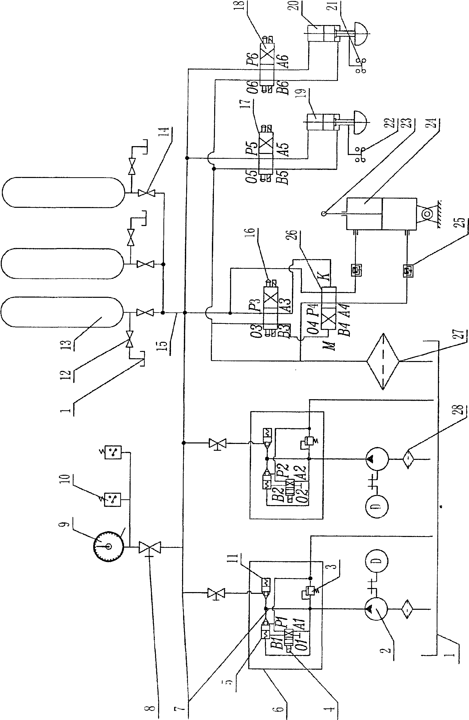
[0008] As shown in the figure, the high-pressure accumulating hydraulic working device of the present invention includes a hydraulic source supply pipeline formed by connecting an oil pump output pipe (7) and an accumulator output pipe (15) in parallel, and is characterized in that: the hydraulic source One of the supply lines passes through the first two-position four-way reversing valve A (26) to control the first working oil cylinder D (24) to realize the drive control of the opening and closing of the butterfly valve (23), and the other way passes through the second two-position four-way reversing valve The valve B (17) controls the second working oil cylinder E (19) to realize the pulling and inserting of the butterfly valve lock pin (22), and the third way controls the third working oil cylinder F (20) through the third two-position four-way rever...


PUM


Abstract

The invention relates to a high-voltage energy-storage hydraulic work device, comprising a hydraulic source supply pipe formed by connecting a scavenge delivery and an accumulator output pipe in parallel, characterized in that: 1,2-position four-way reversal valve A of one path of the hydraulic source supply pipe controls a first operating cylinder D to realize the drive control of a butterfly valve start-stop and 2,3-position four-way reversal valve B of another path controls a second operating cylinder B to realize the pull-out and insert of the butterfly valve lock ingot, the third path controls a third operating cylinder F to realize the drive of a by-pass valve start-stop by a 3,2-position four-way reversal valve. The work device provides stable pressure oil source for the inlet valve hydraulic actuator of hydraulic turbine generator unit, with features of high reliability, compactness and convenient operation; and the system can normally work when the oil pump can not in normal working.

Description

technical field [0001] The invention relates to a high-pressure energy storage hydraulic working device. technical background [0002] The existing water turbine inlet valve control system still adopts the structure of the supplementary air hydraulic device in China. For decades, the cast globe valve has been used as the control element in the control system, and all of them are connected by steel pipelines. The arrangement of components is relatively scattered, resulting in a bulky control device, inconvenient operation, and unfavorable realization of automatic control. In addition, the cast globe valve itself is relatively rough and has poor sealing performance, and the connected pipeline is long and has many pipe joints, so it is prone to leakage, which reduces the reliability of the control device, and even causes misoperation and refusal to operate, which endangers the turbine equipment. safety, leading to the occurrence of power plant accidents. SUMMARY OF THE INVEN...

Claims


Application Information

Patent Timeline
IPC IPC(8): F15B1/02F15B13/02
Inventor 黄新照黄友斌蔡聪荣黄露
Owner 福建省龙杰特电机有限责任公司
Why Eureka
Try Eureka