Single pole moving and swinging type public transportation trolley bus pantograph

A pantograph and bus technology, which is applied in the field of transportation, can solve the problems of unsightly waiting stations for charging trolleybuses, complex forms and structures of pantographs, limited application scope, etc., and achieves simple and reasonable structure, simple structure and composition. The effect of fewer components

Inactive Publication Date: 2009-11-18
SHANGHAI JIAO TONG UNIV
View PDF1 Cites 10 Cited by
  • Summary
  • Abstract
  • Description
  • Claims
  • Application Information

AI Technical Summary

Problems solved by technology

Although this invention adopts the double-wire pantograph power receiving method with the liftable roof of the tram, its automatic lifting and lowering of the double-wire pair has less constraints on the network connection, and can be used for the double-wire power receiving and charging of the rechargeable trolleybus in the station area; but from its Technology "two double-linked planar four-bar linkages" and "when the cylinder on the bottom frame and the bow spring make the lower arm swing, the conductive slide plate on the top of the bow is raised and lowered", and "can be connected to the network while the tram is running It can be seen that the double-wire receiving type pantograph does lifting movement when it is working, and its bow-top conductive slide is powered from the special charging feeder network above the vehicle driving road in the overhead station area. Whether it is drawn from the electric pole on the sidewalk or the shed of the bus waiting station on the street, it still restricts the driving of other super-high vehicles such as some engineering vehicles and special transport vehicles, and the charging The station area of ​​the trolleybus waiting station is not beautiful enough; moreover, the lower arm, tie rod, upper arm, balance bar, bow head cross bar, etc. constitute two double-connected planar four-bar linkages, making the form of the pantograph And the structure is complex, so this kind of technology has defects, and the scope of application is still limited

Method used


Image

  • Single pole moving and swinging type public transportation trolley bus pantograph
  • Single pole moving and swinging type public transportation trolley bus pantograph
  • Single pole moving and swinging type public transportation trolley bus pantograph

Examples


Embodiment Construction

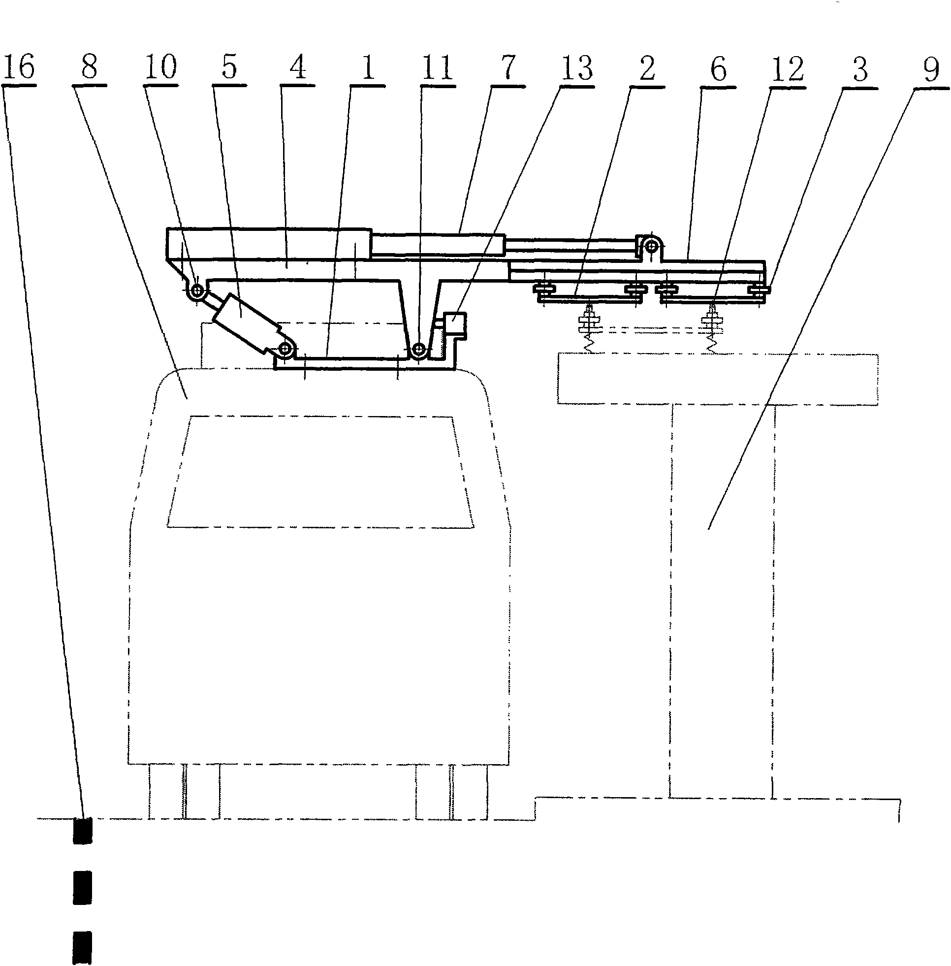
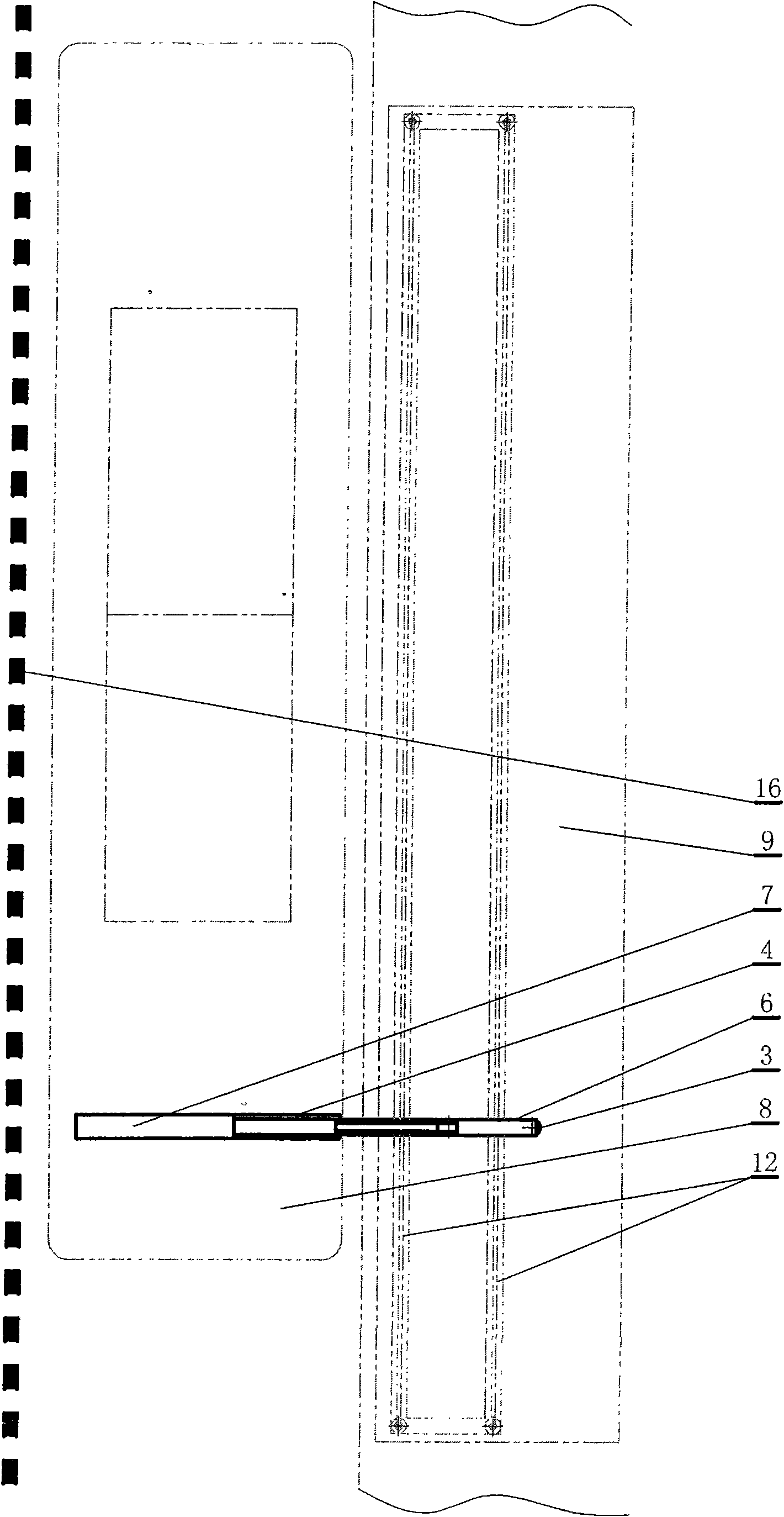
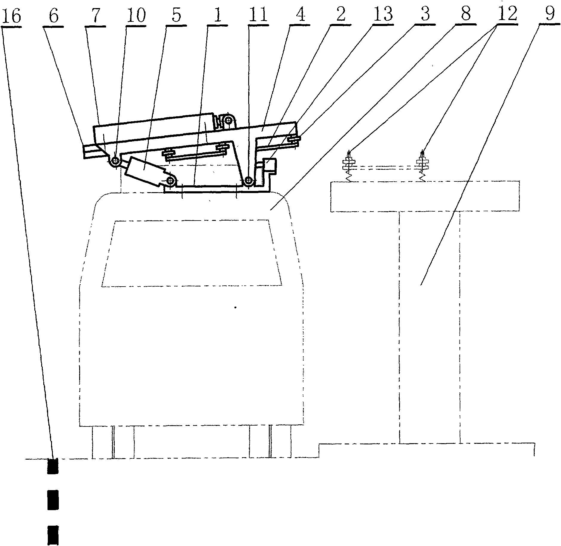
[0017] The embodiments of the present invention are described in detail below in conjunction with the accompanying drawings: this embodiment is implemented on the premise of the technical solution of the present invention, and detailed implementation methods and specific operating procedures are provided, but the protection scope of the present invention is not limited to the following the described embodiment.

[0018] Such as figure 1, figure 2 , image 3, Figure 4, Figure 5 and Figure 6 As shown, this embodiment includes: a chassis 1, a pantograph body 2, an insulator 3, a guide rail frame 4, a swing drive device 5, a bow ejector rod 6, and a bow drive device 7. On the roof or on the roof of the bus and tram waiting station 9, the swing driving device 5 is correspondingly located on the roof of the bus and tram 8 or on the station shed of the bus and tram waiting station 9, and the swing driving device 5 is located on the underframe 1, swing The power output end ...


PUM


Abstract

The invention relates to a single pole moving and swinging type public transportation trolley bus pantograph in the technical field of transportation; in the invention, the power output end of a swinging driving device is connected with a guide rail bracket which is hinged with and supported on a chassis; the chassis is provided with a pantograph top bar and a moving pantograph driving device; the pantograph top bar, under the effect of the moving pantograph driving device, can move in the transverse and lateral directions vertical to the driving direction of the public transportation trolley bus to extend out of the bus roof; bi-polar pantograph bodiesare respectively supported at the lower part of the pantograph top bar by an insulator; the bi-polar pantograph bodies are mutually insulated, thus forming a double power receiving body, the guide rail bracket and the moving pantograph driving device; the pantograph top bar, under the effect of the swinging and driving device, can swing and lift; as a result, the bi-polar pantograph bodies can respectively approach and closely contact the double conductors to receive power. The invention features simple structure, beautiful waiting lounge, no restrictions imposed on passing vehicles and safe and reliable operation.

Description

technical field [0001] The invention relates to a power receiving device of a rechargeable public vehicle in the technical field of transportation, in particular to a single-rod mobile tilting bus trolley pantograph that receives power laterally. Background technique [0002] At present, the bus or trolley bus using supercapacitor energy storage in the field of urban public transportation has entered commercial operation or trial operation, and its vehicle has a small amount of supercapacitor, so the vehicle is light in weight, flexible and fast, and only needs to use the terminal and Short-term fast supplementary charging when parking at some intermediate stops can drive uninterrupted on the entire operating line. Since this technology can mostly cancel the original trolleybus overhead power supply contact wire network or feeder wire network along the bus line, only a section of contact wire network dedicated to charging is reserved above the station area of ​​the terminal ...

Claims


Application Information

Patent Timeline
IPC IPC(8): B60L5/19B60L5/20
CPCB60L2200/26B60L11/185B60M1/36B60L5/19Y02T90/14Y02T10/7088B60M7/003Y02T10/7005B60L11/1801Y02T90/128B60L50/53B60L53/11Y02T10/70Y02T10/7072
Inventor 程晓鸣
Owner SHANGHAI JIAO TONG UNIV
Why Eureka
Try Eureka