
Method for determining a state of a reformer in a fuel cell system

A fuel cell system and recombiner technology, applied in the direction of fuel cells, chemical instruments and methods, electrochemical generators, etc., can solve the problems of fuel cell system damage, fuel cell system life shortening, impossible to determine the state of recombiner, etc. Achieve the effect of low cost and avoid duplication

Inactive Publication Date: 2009-11-25
EHNERDEJ GMBKH
View PDF0 Cites 0 Cited by
  • Summary
  • Abstract
  • Description
  • Claims
  • Application Information

AI Technical Summary

Problems solved by technology

Since it is especially not possible to determine the state of the reformer, damage to the fuel cell system can occur in the event of a reformer error, which can lead to a shortened lifetime of the fuel cell system overall

Method used


Image

  • Method for determining a state of a reformer in a fuel cell system
  • Method for determining a state of a reformer in a fuel cell system
  • Method for determining a state of a reformer in a fuel cell system

Examples


Embodiment Construction

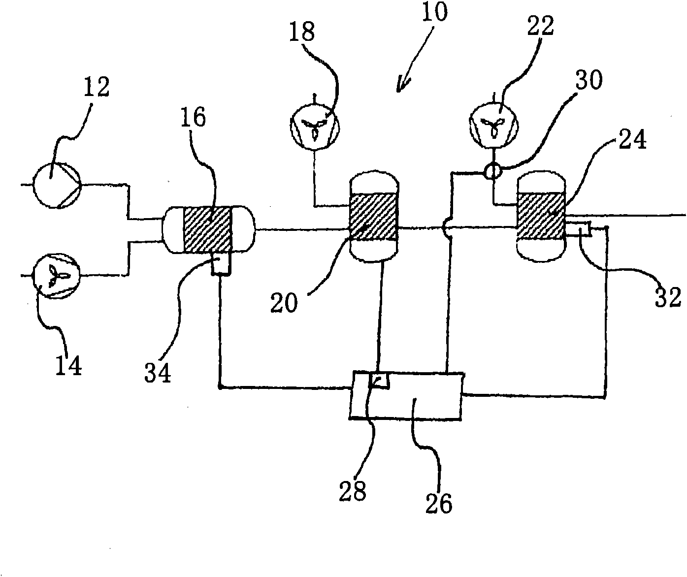
[0015] figure 1 A schematic diagram of a fuel cell system 10 according to the invention is shown. In the case shown, the fuel cell system 10 includes a recombiner 16 , which is coupled for fuel delivery to a upstream fuel supply 12 and for air delivery to an upstream air supply 14 . The reformer 16 is connected to a fuel cell stack 20 provided behind it. The fuel cell stack 20 in this case consists of a plurality of fuel cells. In an alternative embodiment, instead of the fuel cell stack 20 , only a single fuel cell can also be provided. In particular, the reformer 16 is coupled to the anode of the fuel cell stack 20 . Furthermore, the fuel cell stack 20 is connected to a cathode air supply 18 which supplies cathode air to the cathodes of the fuel cell stack 20 . In addition, the fuel cell stack 20 is connected with the afterburner 24, and in this embodiment, not only the exhaust gas generated from the anode of the fuel cell stack 20 can be delivered to the afterburner, bu...


PUM


Abstract

The invention relates to a method for determining a state of a reformer (16) in a fuel cell system (10). According to the invention, the state of the reformer (16) is determined based on one or more predetermined characteristic curves correlated with anode efficiency.

Description

technical field [0001] The invention relates to a method for determining the state of a reformer in a fuel cell system. [0002] The invention also relates to a fuel cell system with a control device. Background technique [0003] Fuel cell systems are generally known, such as SOFC fuel cell systems (SOFC stands for Solid Oxide Fuel Cell), in which a reformer, a fuel cell or a fuel cell stack and an afterburner are interconnected in this order. The reformer converts the air and combustible substances fed into it into a gas or reformate containing hydrogen and carbon monoxide. The reformate then reaches the anode of the fuel cell or fuel cell stack. The reformate is delivered to the fuel cell stack, in particular via the anode input. In the anode, the recombinant (H 2 , CO) is catalyzed and oxidized by releasing electrons and output through the anode output terminal. The electrons are removed from the fuel cell or fuel cell stack and flow, for example, to an electron loa...

Claims


Application Information

Patent Timeline
IPC IPC(8): H01M8/06
CPCH01M8/0618H01M8/04447H01M8/04462H01M8/04373Y02E60/50H01M8/04589C01B2203/066H01M8/0444C01B3/34C01B2203/1685H01M8/04425Y02E60/525H01M2008/1293
Inventor 斯特凡·凯丁周苏
Owner EHNERDEJ GMBKH
Learn More