Supercharge Your Innovation With Domain-Expert AI Agents!

Tube drawing machine

A pipe machine and shell technology, applied in the field of old pipes, can solve the problems of low efficiency, labor and time-consuming, difficult operation, etc., and achieve the effects of high efficiency, good effect and fast pipe extraction speed.

Inactive Publication Date: 2010-02-10
HARBIN TIANTAI TECH
View PDF0 Cites 1 Cited by
  • Summary
  • Abstract
  • Description
  • Claims
  • Application Information

AI Technical Summary

Problems solved by technology

[0002] At present, in the process of replacing the old tubes of the heat exchanger with new tubes, after the old tubes are pulled out of the tube heads, most of them are pulled out manually one by one. Time-consuming, difficult operation and extremely low efficiency

Method used


Image

  • Tube drawing machine
  • Tube drawing machine
  • Tube drawing machine

Examples


Embodiment Construction

[0010] Embodiments of the present invention will be further described in detail below in conjunction with the accompanying drawings.

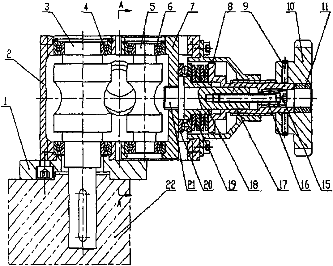
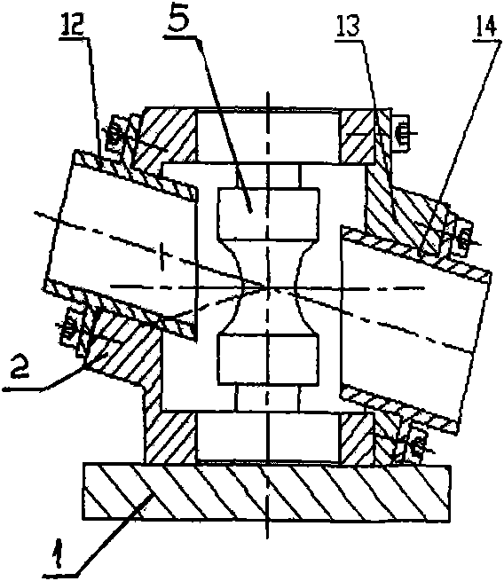
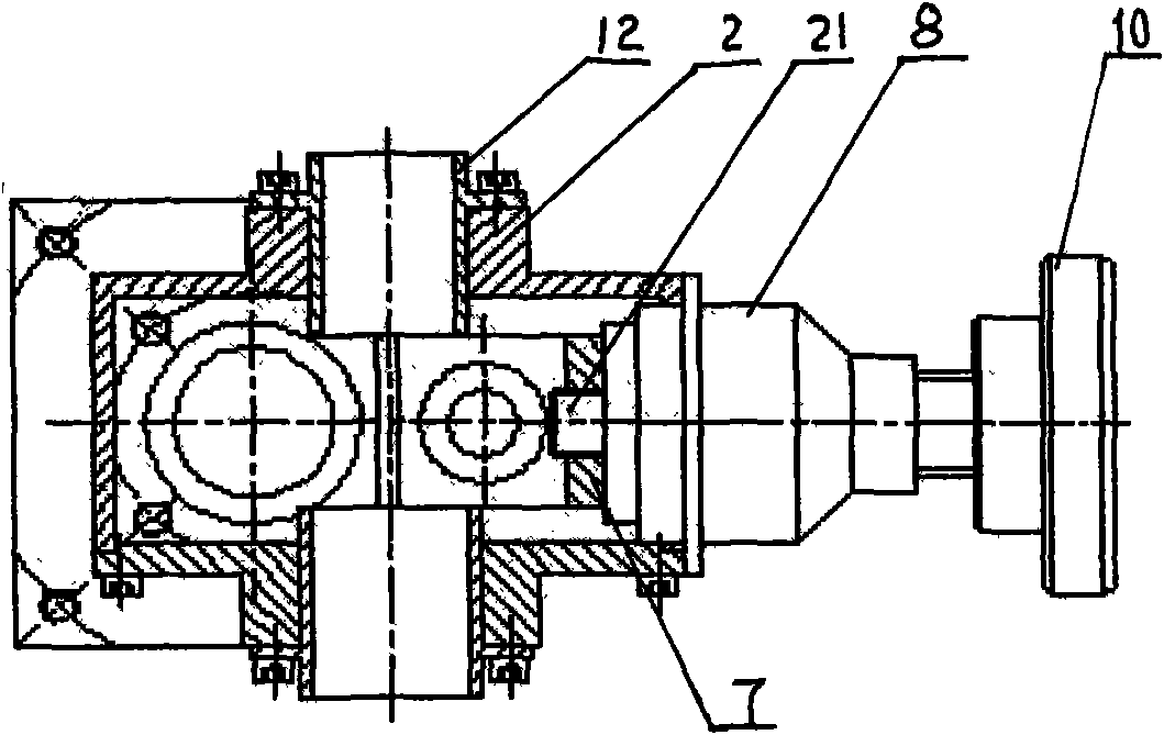
[0011] Depend on Figure 1-Figure 3 It can be seen that the lower end of the housing 2 of the present invention is connected to the motor 22 by bolts connecting the backing plate 1, the driving wheel 3 is radially installed in the housing 2 cavity, and the sliding frame 7 is arranged on the right side of the housing 2 cavity, and the radial direction is equipped with The driven wheel 5 and the right end of the sliding frame 7 are fixed with a base column 21, and the right side of the base column 21 shaft shoulder is sleeved with a transition sleeve 18, on which a thrust bearing 20, a butterfly spring 19, a guide sleeve 17, and a base column 21 are arranged in sequence. Screw 9 and hand wheel 10 are passed through the right side end, screw rod 15 is installed in the inner cavity of base column 21, spring 16 is set on its outer wall, inclined thr...


PUM


Abstract

The invention relates to a tube drawing machine, the lower end of a housing is connected with a motor through a bolt connection pad, a driving wheel is radially arranged in a cavity of the housing, asliding support is arranged on the right side of the inner cavity of the housing, a driven wheel is radially arranged therein, a base pillar is fixedly arranged at the right end of the sliding support, a transition sleeve is sheathed on the right side of a shaft shoulder of the base pillar, a thrust bearing, a disc spring and guide sleeves are sequentially arranged on the transition sleeve, the end part of the right side of the base pillar passes through a screw and a handwheel, a screw rod is arranged in the inner cavity of the base pillar, the spring is sheathed on the outer wall of the screw rod, inclined through holes are formed on the front end surface and the back end surface of the housing, and the front guide sleeve and the back guide sleeve are fixedly arranged in the through holes. The tube drawing machine has the advantages of compact structure, reasonable design, full utilization of principles of friction force, rapid tube drawing speed and high efficiency.

Description

technical field [0001] The invention is suitable for extracting stuck old tubes during the tube exchange process of various heat exchangers. Background technique [0002] At present, in the process of replacing the old tubes of the heat exchanger with new tubes, after the old tubes are pulled out of the tube heads, most of them are pulled out manually one by one. Time-consuming, difficult to operate, extremely low efficiency. Contents of the invention [0003] The object of the present invention is to overcome the disadvantages in the above-mentioned technology, and provide a pipe extractor with compact structure and reasonable design, which can extract the jammed pipe from the condenser under the action of friction. [0004] In order to achieve the above purpose, the technical solution adopted by the present invention is: the lower end of the housing is connected to the motor through a bolted backing plate, the driving wheel is radially installed in the housing cavity, a...

Claims


Application Information

Patent Timeline
IPC IPC(8): B23P19/04
Inventor 丁永生
Owner HARBIN TIANTAI TECH
Features
  • R&D
  • Intellectual Property
  • Life Sciences
  • Materials
  • Tech Scout
  • Unparalleled Data Quality
  • Higher Quality Content
  • 60% Fewer Hallucinations
Learn More