Distribution type method for protecting residual current of low voltage power supply system

A technology of residual current and power supply system, which is applied in the direction of electrical signal transmission system, signal transmission system, information technology support system, etc., which can solve the difficulty of correct identification of residual current, inability to operate correctly, and reduce the safety level of TN-C grounding power supply system and other problems, to achieve the effect that the method is practical, reduces the error rate, and improves the reliability of power supply

Active Publication Date: 2010-04-28
CHINA ELECTRIC POWER RES INST +1
View PDF0 Cites 13 Cited by
  • Summary
  • Abstract
  • Description
  • Claims
  • Application Information

AI Technical Summary

Problems solved by technology

At present, there are more and more low-voltage lines in rural areas using insulated wires and grounding methods using TN-C systems, and the existing residual current protection devices are increasingly unable to meet actual needs. Due to the aforementioned reasons, the first-level leakage protection and the second-level leakage protection device cannot operate correctly, thus reducing the safety level of

Method used


Image

  • Distribution type method for protecting residual current of low voltage power supply system
  • Distribution type method for protecting residual current of low voltage power supply system

Examples


Example Embodiment

[0036] Implementation mode one

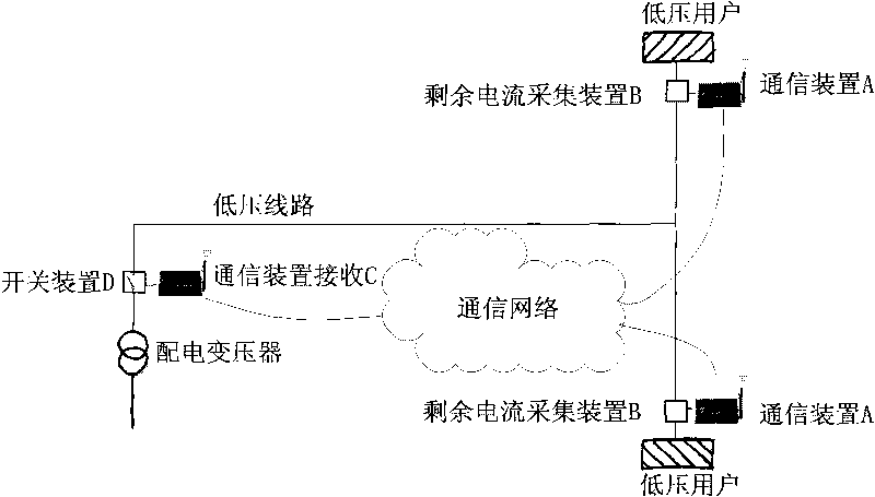
[0037] (1) Install a wireless sensor communication (WSN) device A at the user terminal, and install a residual current collecting device B at the incoming line of the user terminal. The residual current collected by the residual current collecting device B can be transmitted to the wireless sensor communication in real time (WSN) device A, wireless sensor communication (WSN) device A has the functions of processing and identifying the received residual current and counting the duration.

[0038] (2) Install wireless sensor communication (WSN) receiving device C and residual current protection device D on the low-voltage side of the distribution transformer. The wireless sensor communication receiving device C can receive the signal sent by the wireless sensor communication (WSN) receiving device A, and process the received information within the allowed time, and can send the command to cut off the power line to the residual current Protection devi...

Example Embodiment

[0040] Implementation mode two

[0041] Communication device A uses wired communication device A or wireless communication device A or carrier communication device A, and communication receiving device C uses wired communication receiving device C or wireless communication receiving device C or carrier communication receiving device C. Others are the same as the first embodiment.

Example Embodiment

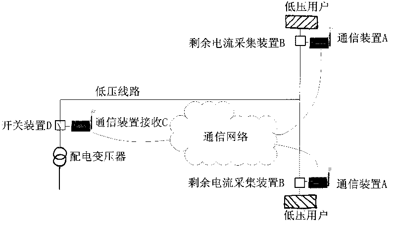
[0042] Implementation mode three

[0043] The communication receiving device C and the residual current protection device D are installed at the low-voltage line branch, and the others are the same as the first or second embodiment.


PUM


Abstract

The invention provides a distribution type method for protecting residual current for solving the problems of high malfunction rate or accurate action incapability of a residual current protective device. The method comprises the following steps that the residual current and duration time of the residual current of the residual current protective device are acquired; information is sent in real time to a superior residual current protective device; and the superior residual current protective device determines whether to act or not according to the received information so as to realize multi-grade cooperation for residual current protection and effectively reduce the malfunction rate of the residual current protective devices.

Description

technical field [0001] The invention relates to the field of leakage protection of a low-voltage power supply system, in particular to a residual current protection method for a distributed low-voltage power supply system. Background technique [0002] The current residual current protection method is an in-situ protection method, that is, according to the information directly collected by the residual current protection, it is judged whether the residual current exceeds the standard, and then it is judged whether an action is required. This residual current protection method has certain problems in practical application, especially the protection on the side of the distribution transformer and the protection at the branch of the low-voltage line are not ideal, mainly manifested in the high rate of false trips, or the inability to operate correctly according to the needs. protected situation. [0003] Taking the current-type residual current protection device as an example,...

Claims


Application Information

Patent Timeline
IPC IPC(8): H02J13/00G08C17/02G08C19/00
CPCY04S40/126Y04S40/143Y02B90/2684Y04S40/127Y02E60/7884Y02B90/2653Y02E60/7853Y02E60/7861Y02B90/20Y02E60/00
Inventor 宋晓辉盛万兴孙军平
Owner CHINA ELECTRIC POWER RES INST
Why Eureka
Try Eureka