Check patentability & draft patents in minutes with Patsnap Eureka AI!

Fixed component

A technology for fixing components and fixing frames, which is applied in the directions of printing, printing devices, etc., can solve the problems of inconvenient installation of the box structure, and achieve the effects of good consistency, avoidance of damage, and moderate strength.

Active Publication Date: 2010-08-18
BEIJING SPIRIT TECH DEV
View PDF4 Cites 1 Cited by
  • Summary
  • Abstract
  • Description
  • Claims
  • Application Information

AI Technical Summary

Problems solved by technology

[0007] Aiming at the problem of inconvenient installation when the box structure is embedded in other instruments in the prior art, the present invention provides a fixing assembly

Method used


Image

  • Fixed component
  • Fixed component
  • Fixed component

Examples


Embodiment Construction

[0020] In order to make the object, technical solution and advantages of the present invention clearer, the implementation manner of the present invention will be further described in detail below in conjunction with the accompanying drawings.

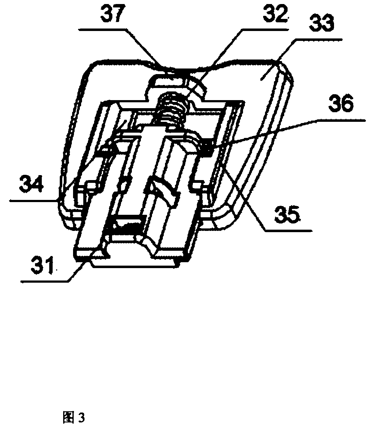
[0021] Such as Figure 3 to Figure 6 As shown, the fixing assembly provided by the embodiment of the present invention is mainly composed of three parts, which are a fixing frame 31 , a spring 32 and a supporting member 33 . The main body of the support 33 is a flat plate structure, and a strip slideway 34 is formed in the middle of the upper surface of the support piece 33. One end of the strip slideway 34 extends to the top of the support piece 31, and a baffle plate 37 is provided on the top of the other end. Limiting points 35 are symmetrically arranged on the edge of the strip slideway 34 and higher than the slideway position. A spring limiting column 39 is arranged at the center of the slideway 34 for limiting the movement path ...


PUM


Abstract

The invention discloses a fixed component belonging to the field of machinery manufacture. The fixed component comprises a fixed mount, a spring and a supporting piece, wherein the fixed mount can slide in a slide rail on the support piece; the edge of the slide rail of the supporting piece is provided with a limit point, and the limit point is matched with a limit baffle of the fixed mount to ensure that the supporting piece and the fixed mount can not slip off from each other; the spring is connected between the supporting piece and the fixed mount so as to push the supporting piece and the fixed mount to opposite directions; the back surface of the fixed mount is provided with a connecting device; and the fixed component is fixed on a box body structure to be installed. The fixed component is formed into a whole by a specific structure, and the phenomenon that components slip off from each other can not happen, and therefore, the installation and the operation can be completely finished by one hand; the fixed component is extremely convenient and is suitable for installing instruments with limited space. Meanwhile, the clamp forces of the fixed component and the frame of the box body to be installed to the panel of a host machine are provided by the spring, and thereby, the fixed component can not be influenced by manual operation, and damage can not be created on the panel of a large-size machine.

Description

technical field [0001] The invention relates to the field of mechanical manufacturing, in particular to a fixing assembly. Background technique [0002] With the continuous expansion of demand, micro-printers have been widely used in various industries, such as instrumentation, supermarkets, convenience stores, postal services, banks and other systems. As a printout device, the micro-printer is usually embedded and fixed in the notch of the panel opening of the instrument or the main body of the device. [0003] The micro-printer and the host are usually fixed in the following two ways: [0004] The first such as figure 1 As shown: the surface where the micro-printer casing 2 is attached to the installation panel of the host body is provided with an installation frame 21 . At the same time, a specific mechanism is provided on the outer surface of the micro-printer casing 2 extending into the notch of the host machine body for fixing the installation lug 3 . After the mic...

Claims


Application Information

Patent Timeline
Patent Type & Authority Applications(China)
IPC IPC(8): B41J29/04
Inventor 孙小柱高宇春
Owner BEIJING SPIRIT TECH DEV
Features
  • R&D
  • Intellectual Property
  • Life Sciences
  • Materials
  • Tech Scout
  • Unparalleled Data Quality
  • Higher Quality Content
  • 60% Fewer Hallucinations
Learn More