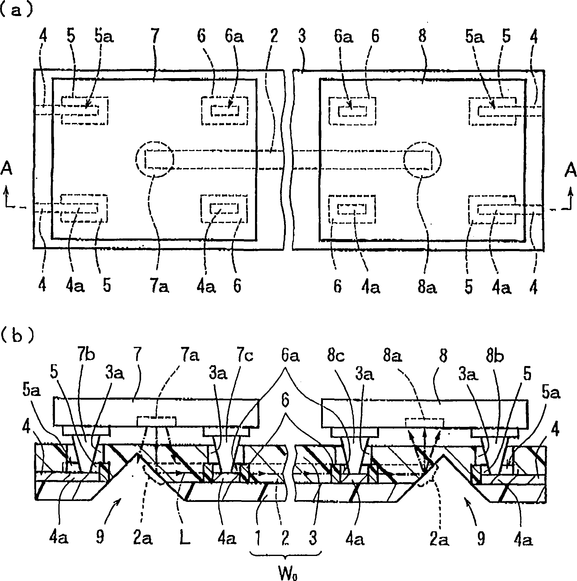
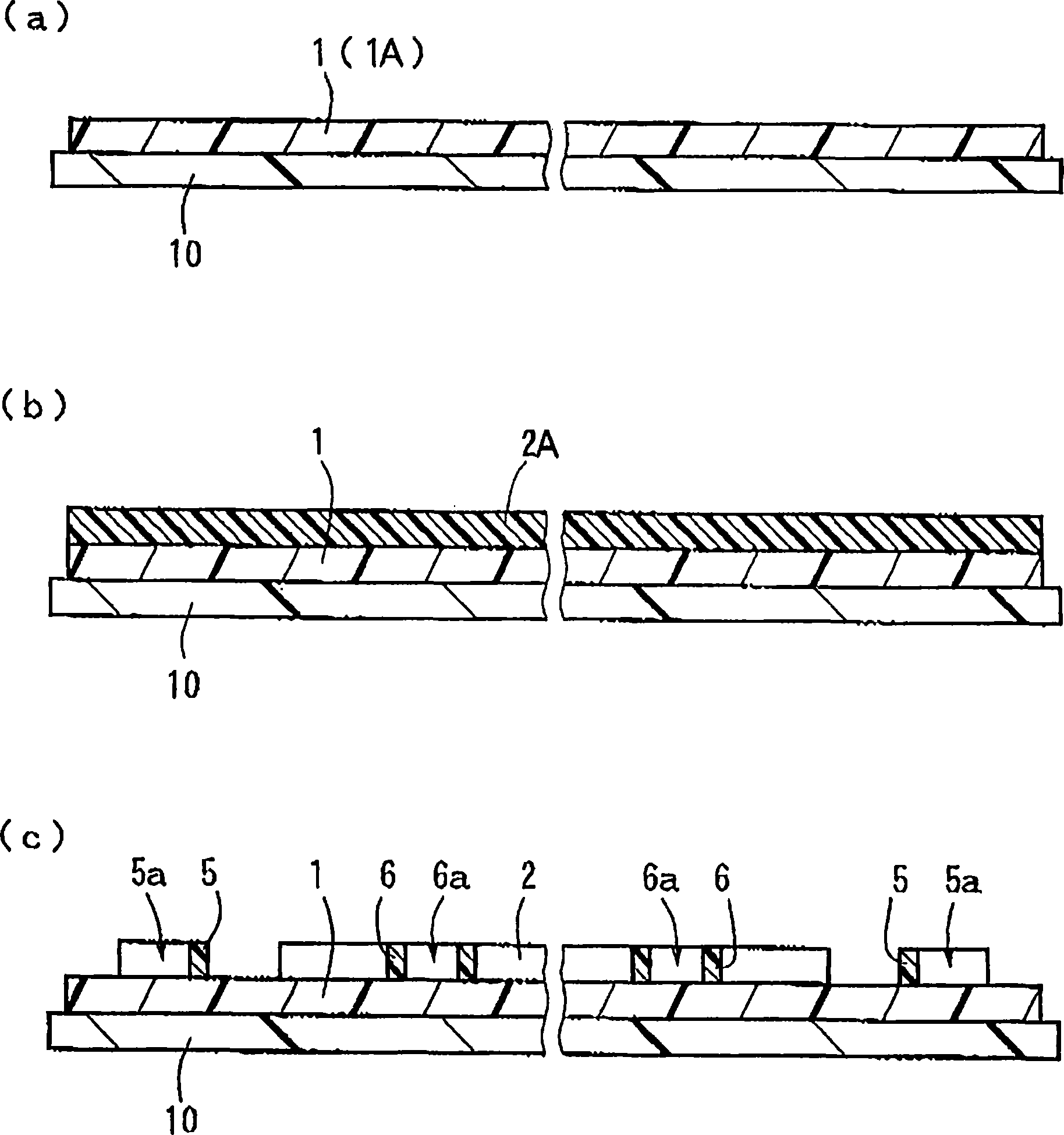
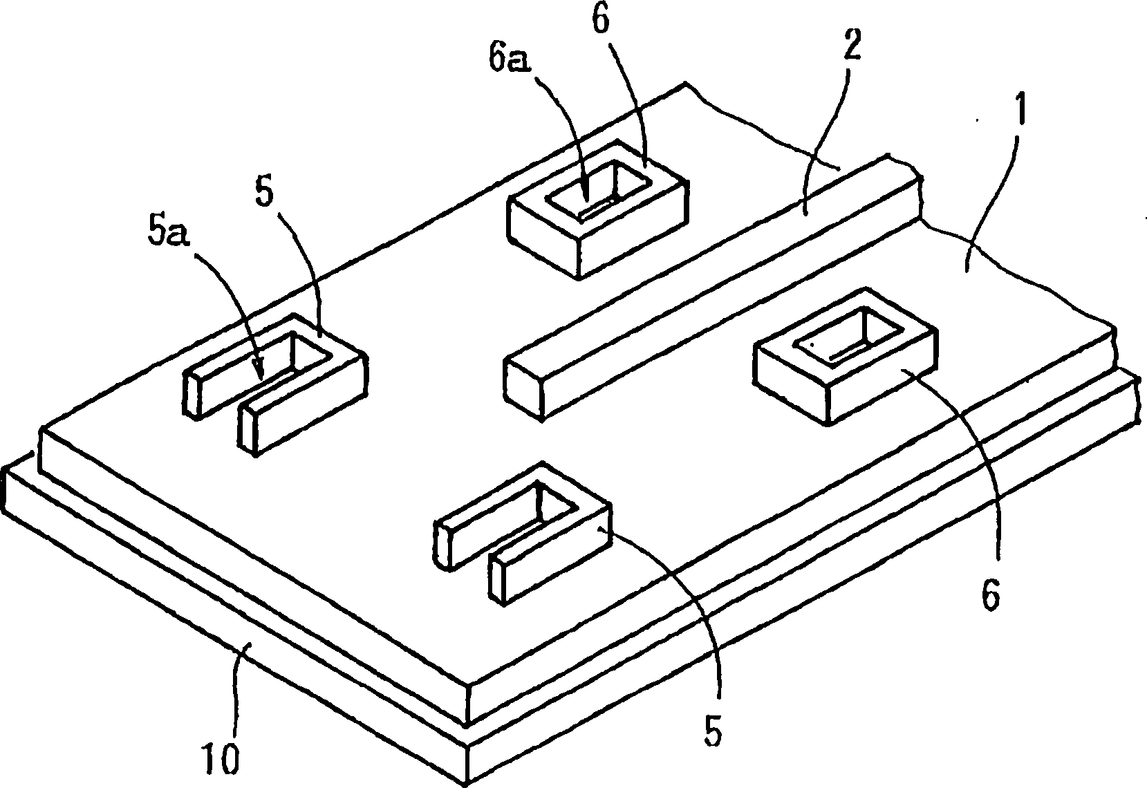
Method of manufacturing Opto-electric hybrid module
A technology of optoelectronic hybrid loading and manufacturing method, which is applied in the direction of electrical components, coupling of optical waveguides, printed circuit components, etc., to achieve the effects of high installation accuracy, improved optical coupling efficiency, and shortened distances
- Summary
- Abstract
- Description
- Claims
- Application Information
AI Technical Summary
Problems solved by technology
Method used
Image

Examples
Embodiment
[0050] [Materials for forming the under cladding layer and the over cladding layer]
[0051] Through 35 parts by weight of bisphenoxyethanolfluorine glycidye ether (bisphenoxyethanolfluorine glycidye ether) (ingredient A), ester ring type epoxy resin 3', 4'-epoxycyclohexylmethyl-3,4-epoxy Cyclohexyl carboxylate (CELLOXIDE 2021P manufactured by DAICEL Chemical Industry Co., Ltd.) (component B) 40 parts by weight, (3',4'-epoxycyclohexane)methyl-3',4'-epoxycyclohexyl methyl Acetate (manufactured by DAICEL Chemical Industry Co., Ltd., CELLOXIDE 2081) (component C) 25 parts by weight, 4,4'-bis[bis(β-hydroxyethoxy)phenylsulfinyl]phenylsulfide-bis-hexa 2 parts by weight of a 50% by weight propioncarbonate (Japanese name: Propionka-Bonet) solution (component D) of fluoroantimonate was mixed to prepare materials for forming the lower cladding layer and the upper cladding layer.
[0052] [Formation material of core and bump positioning guide]
[0053] By adding the above component A: ...
PUM
 Abstract
Description
Claims
Application Information
 - R&D
- Intellectual Property
- Life Sciences
- Materials
- Tech Scout
- Unparalleled Data Quality
- Higher Quality Content
- 60% Fewer Hallucinations
Browse by: Latest US Patents, China's latest patents, Technical Efficacy Thesaurus, Application Domain, Technology Topic, Popular Technical Reports.
© 2025 PatSnap. All rights reserved.Legal|Privacy policy|Modern Slavery Act Transparency Statement|Sitemap|About US| Contact US: help@patsnap.com