Optical element, manufacturing method thereof and backlight module

A technology of optical components and manufacturing methods, applied in optical components, optics, nonlinear optics, etc., can solve problems such as spacing and thickness specifications, and inability to optimize designs, so as to achieve the effect of eliminating moiré patterns and optimizing designs

Active Publication Date: 2010-09-01
ENTIRE TECH CO LTD
View PDF1 Cites 2 Cited by
  • Summary
  • Abstract
  • Description
  • Claims
  • Application Information

AI Technical Summary

Problems solved by technology

However, it does not regulate the interval and thickness of the reflective structure 13',

Method used


Image

  • Optical element, manufacturing method thereof and backlight module
  • Optical element, manufacturing method thereof and backlight module
  • Optical element, manufacturing method thereof and backlight module

Examples


Example Embodiment

In the following embodiments, the x-axis direction will represent the second direction, and the y-axis direction will represent the first direction. However, those of ordinary skill in the art can understand that this is only for the convenience of presentation, not the first direction and the first direction. Limitations made by the two directions.

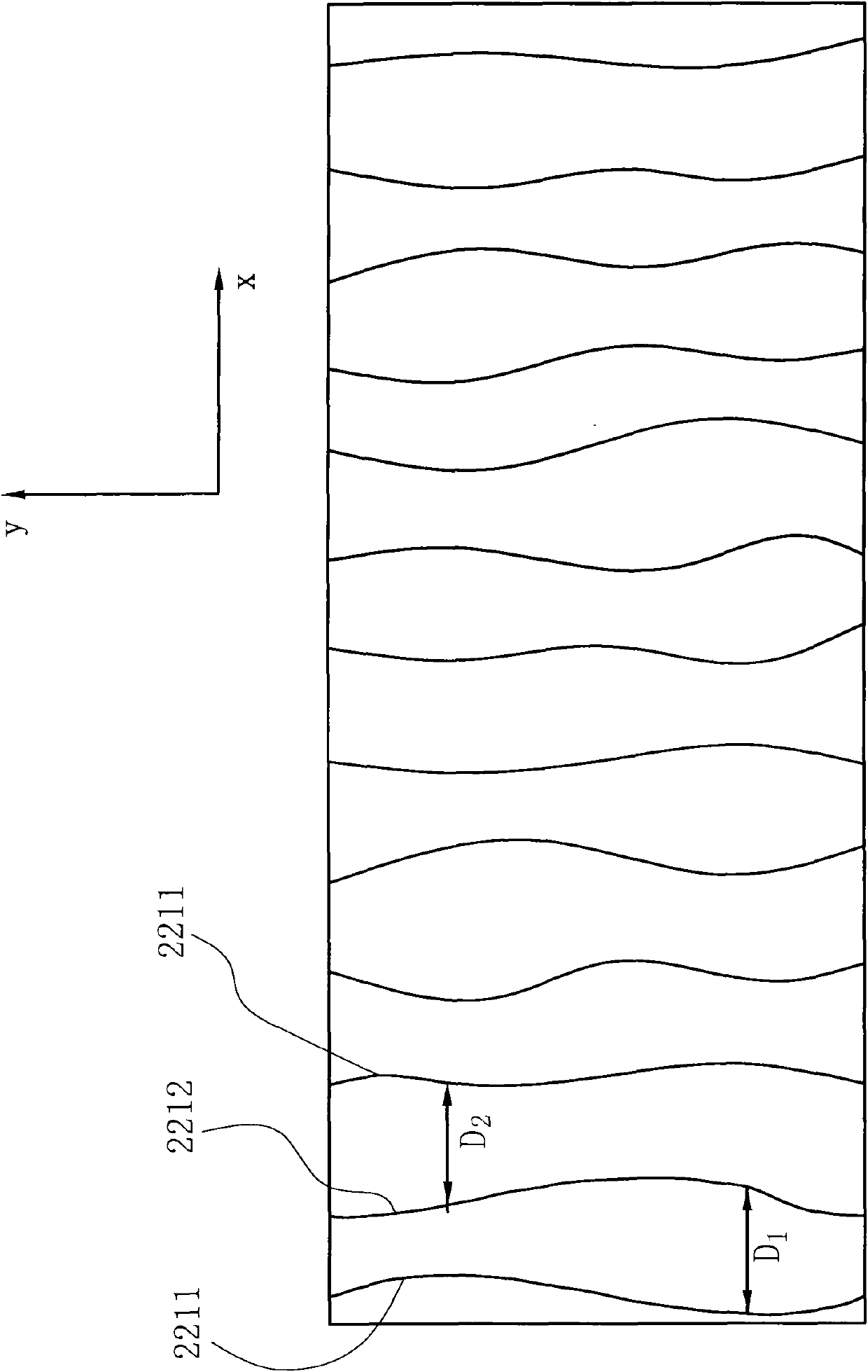
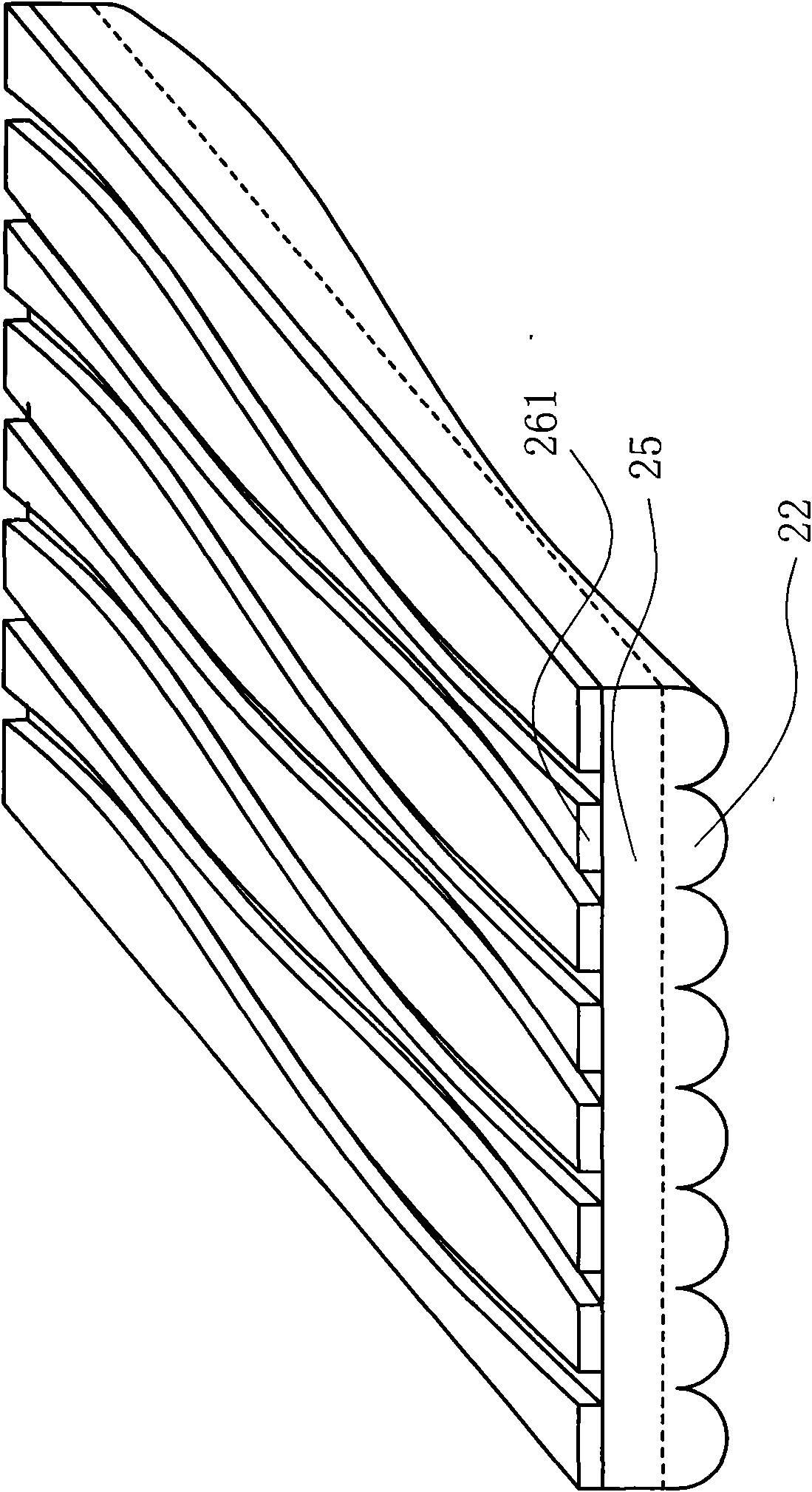
Please refer to FIG. 2. FIG. 2 is a perspective view of the optical element according to the first embodiment of the present invention. The optical element 2 is substantially in the shape of a thin plate, which is, for example, arranged above the diffuser in the direct-lit backlight module, that is, on the light-emitting surface side of the diffuser. The light-emitting surface 21 of the optical element 2 has a plurality of microstructures 22, and the microstructures 22 are arranged on the light-emitting surface 21 along the X direction, and each microstructure 22 has a top edge 221. The function of these microstructures 22 is to co...


PUM


Abstract

The invention provides an optical element, a manufacturing method thereof and a backlight module. The backlight module comprises the optical element. The optical element comprises a plurality of microstructures and a plurality of reflecting structures, wherein the microstructures extend along a first direction and are arranged on a light emergent surface along a second direction; the distance between a first curve and a second curve is unequal and not parallel in the second direction; the distance between the second curve and another first curve is unequal and not parallel in the second direction; the reflecting structures extend along the first direction and are arranged on a light incident surface along the second direction, and the position of each reflecting structure corresponds to the joint of two microstructures; a thickness exists from each reflecting structure to the light incident surface; and the length of the microstructures along the second direction is a width P, which meets the following formula with a refractive index n of the optical element. When the design of the optical element meets the formula, the optical effect is better.

Description

technical field The invention relates to an optical element, its manufacturing method and a backlight module, in particular to an optical element with a microstructure and a reflective structure, its manufacturing method and a backlight module. Background technique FIG. 1 is a partial cross-sectional view of the brightness enhancement film in US7309149. Referring to FIG. 1, the light incident surface 12' of the brightness enhancement film 1' includes a reflective structure 13', when the first light L1, the second light L2 and the third light L3 are incident on the light incident surface 12 of the brightness enhancement film 1' Afterwards, the first light L1 is refracted toward the front of the brightness enhancement film 1', the second light L2 is reflected from the reflective structure 13', and the third light L3 is reflected by the reflective structure 13' or the prism unit 11'. The reflected second light L2 and third light L3 are reflected again by a reflective plate (no...

Claims


Application Information

Patent Timeline
IPC IPC(8): G02B6/00G02B27/00F21V8/00G02F1/13357
Inventor 陈晏佐郑文峰王君伟黄致维林晟
Owner ENTIRE TECH CO LTD
Why Eureka
Try Eureka