
New component insertion technology applied to rapid rotary braiding machine

A technology of components and technology, which is applied in the field of insertion and sealing devices, can solve problems that affect the working efficiency of the braiding machine, braiding errors, equipment downtime, etc.

Inactive Publication Date: 2010-09-15
CHINTOP MICROELECTRONICS SHANGHAI +2
View PDF0 Cites 2 Cited by
  • Summary
  • Abstract
  • Description
  • Claims
  • Application Information

AI Technical Summary

Problems solved by technology

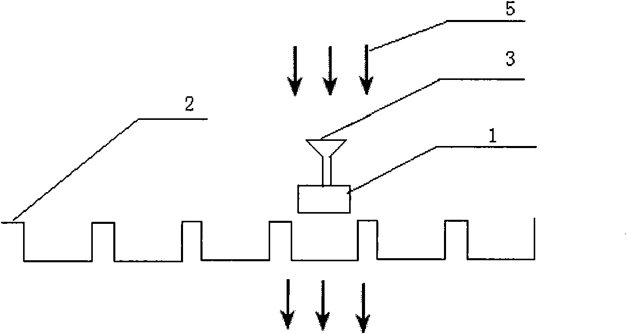
In the current technology, the suction nozzle only performs blowing action when putting the components into the groove of the carrier tape. It is easy to blow the components over and place them tilted, resulting in problems such as braiding errors, equipment shutdown and carrier tape damage. , affecting the working efficiency of the braiding machine

Method used


Image

  • New component insertion technology applied to rapid rotary braiding machine
  • New component insertion technology applied to rapid rotary braiding machine
  • New component insertion technology applied to rapid rotary braiding machine

Examples


Embodiment Construction

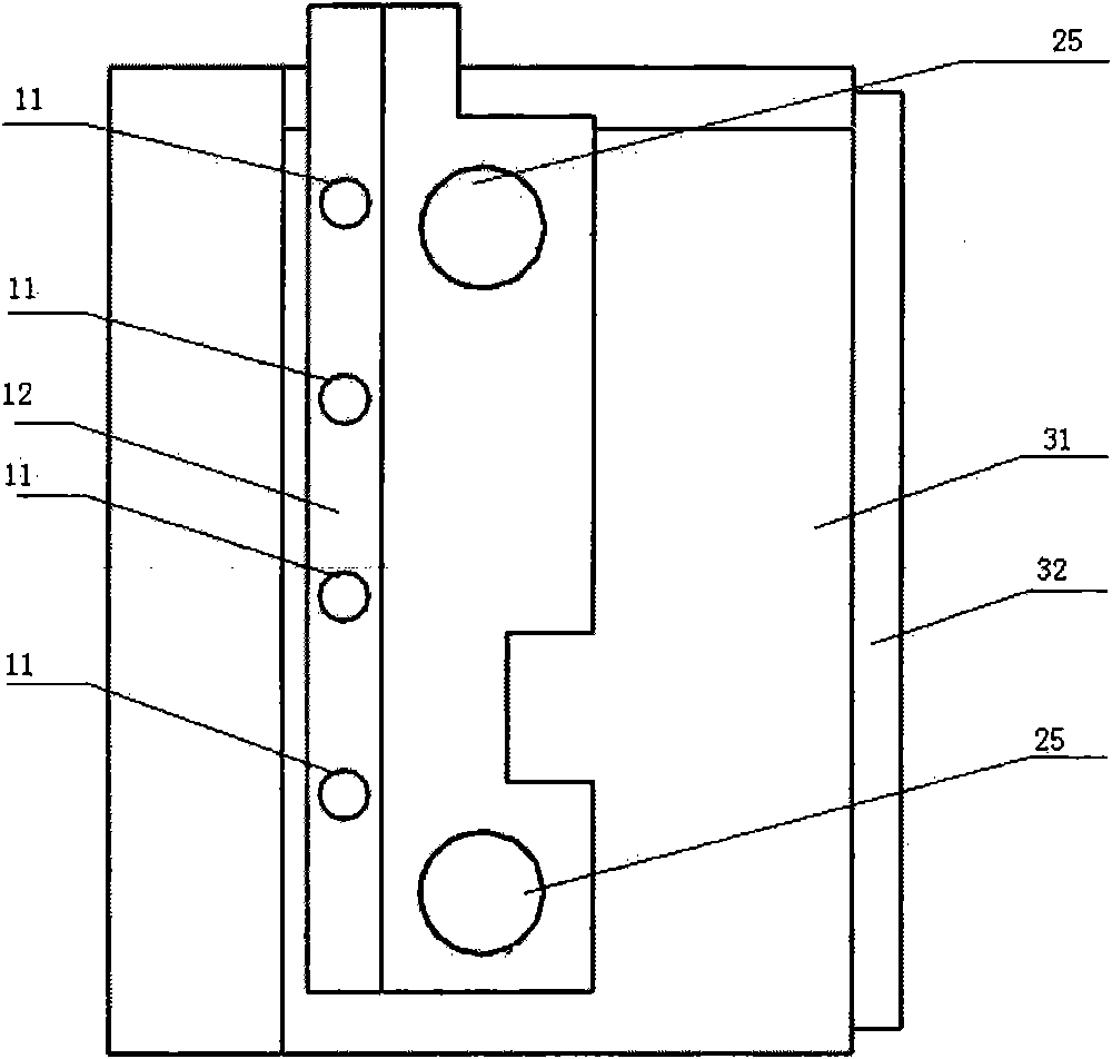
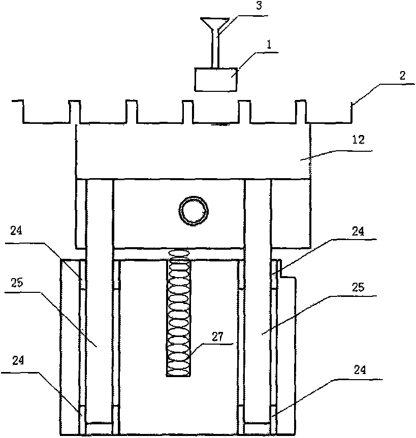
[0007] Figure 2 to Figure 6 It is the suction device of the present invention, and the base 32 installs the suction device on the braiding machine platform of the braiding machine. The sliding sleeve 24 that plays a supporting role is loaded into the abutment 31 to support the guide rod 25, and this device is easy to disassemble. The vacuum negative pressure is connected through the vacuum inlet 13, so that the entire vacuum cavity 12 is in a negative pressure state. The base 31 is equipped with a spring 27 with a certain elastic force, so that the vacuum cavity 12 is closely combined with the carrier tape 2, and the adsorption hole 11 is aligned with the small hole on the bottom surface of the carrier tape. After the suction nozzle 3 moves above the braiding station, it moves downward to insert the component 1 into the carrier tape 2. At this time, the suction nozzle 3 closes the vacuum and blows air to release the component 1. At the same time, the adsorption hole 11. Fir...


PUM


Abstract

The invention relates to a new component braid insertion technology which has the key points that: 1. an adsorption device is arranged below a component placement area or a downwards-blowing device is arranged above the component placement area so as to effectively prevent the problems of components turn-over or incapability of being inserted into carrier-band grooves, and the like; 2. aiming to a carrier-band with holes at the bottom, the adsorption device is arranged below the component placement area; 3. aiming to a carrier-band without holes at the bottom, the downwards-blowing device is arranged above the component placement area; 4. the adsorption device comprises one or more adsorption holes, and the downwards-blowing device can be provided with a plurality of blowing rings and can be simultaneously inserted into the carrier-band grooves corresponding to one or more components; 5. the adsorption device is arranged below the carrier-band, thereby occupying no extra space; 6. the adsorption device and the downwards-blowing device are in leakage along with the positions of a suction nozzle and the components and only work when the suction nozzle inserts the components in, thereby not influencing other components; and 7. the related devices in the technology have simple structure and low cost and are practical and effective.

Description

technical field [0001] The invention relates to an insertion and sealing device for automatic appearance detection of electronic components and braiding and packaging equipment (taping machine). The invention is mainly applied to (but not limited to) the taping and packaging process of various electronic components. This technology can quickly and stably insert the components into the groove of the carrier tape, and can effectively prevent the components from being blown over by the suction nozzle when the components are put into the groove of the carrier tape. Wait for the error. Background technique [0002] Fully automatic electronic component appearance inspection and taping and packaging equipment play an important role in the production of electronic components such as crystal oscillators, capacitors, inductors and resistors, semiconductor discrete devices, and semiconductor integrated circuits. Today's tape machines are running at ever higher speeds and producing sm...

Claims


Application Information

Patent Timeline
IPC IPC(8): B65B15/04
Inventor 王通宙张健欣
Owner CHINTOP MICROELECTRONICS SHANGHAI
Learn More