Check patentability & draft patents in minutes with Patsnap Eureka AI!

Light receiving and image detecting system

An imaging and detection device technology, applied in the field of light-receiving and image detection systems, can solve the problems of unsynchronized and mutated operating procedures.

Active Publication Date: 2012-08-29
MPI CORP
View PDF6 Cites 0 Cited by
  • Summary
  • Abstract
  • Description
  • Claims
  • Application Information

AI Technical Summary

Problems solved by technology

However, since the operating procedures cannot be synchronized, the position of the object under test 21 on the adhesive film may vary with time, and the operating positions of the image detection device 24 and the light receiver 25 are difficult to be moved by the moving mechanism Perfect handling in the same place, thus causing the problem of repeatability of test data

Method used


Image

  • Light receiving and image detecting system
  • Light receiving and image detecting system
  • Light receiving and image detecting system

Examples


Embodiment Construction

[0050] The technical means of the present invention will be described in detail as follows. It is believed that the purpose, characteristics and characteristics of the present invention can be obtained from this in-depth and specific understanding. However, the following examples and illustrations are only provided for reference and illustration, and are not used to explain the present invention. be restricted.

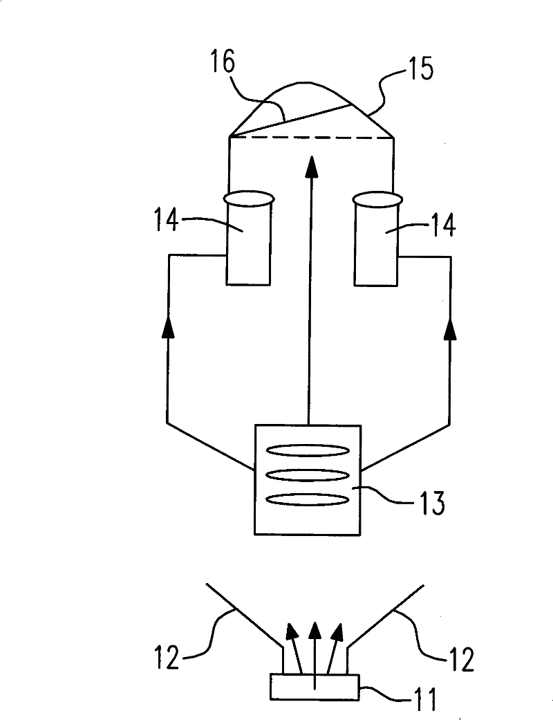
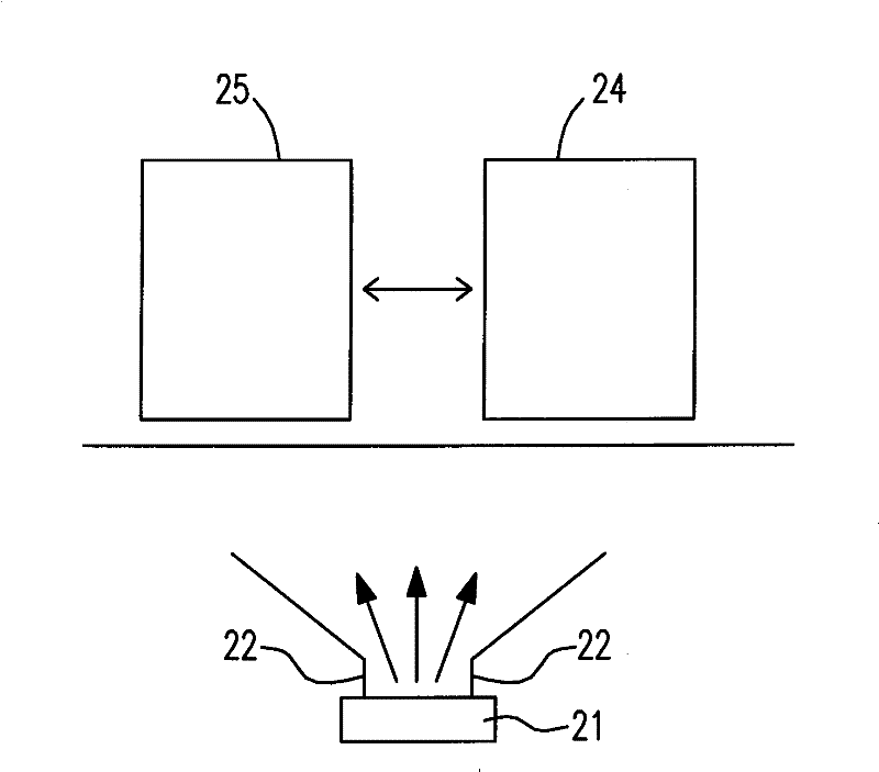
[0051] See first image 3 , which is a structural schematic diagram of an embodiment of the light collection and image detection system and the method for testing light-emitting elements of the present invention. Such as image 3 As shown, an object under test 31 , such as a light-emitting element represented by a light-emitting diode chip, receives the operating electric energy transmitted from the two probes 32 and emits light. In terms of different applications, the type of the object under test 31 includes other types of light emitting elements besides electroni...


PUM


Abstract

The invention provides a light receiving and image detecting system, which comprises a first light splitting device, a second light splitting device and an image detecting device, wherein, the first light splitting device is used for receiving light of objects to be detected, and for distributing the light into a first divided beam and a second divided beam; the second light splitting device is used for receiving the second divided beam, and for distributing the second divided beam into a third divided beam and a fourth divided beam; the image detecting device is used for receiving the fourthdivided beam, and for transforming the fourth divided beam into a digital signal; and preferably, the first divided beam is used for measuring a spectrum, and the third divided beam is used in a light energy test. The light receiving and image detecting system provided by the invention has synchronous operation function and better light splitting effect.

Description

technical field [0001] The invention relates to a light collection and image detection system, in particular to a light collection test and image detection system for testing the light source generated by the light emitting element. Background technique [0002] Light-emitting components are mainly represented by light-emitting diodes, which are currently the electronic components with the best luminous efficiency on the market. Using the mature integrated circuit manufacturing technology for production, the industry can quickly mass-produce light-emitting diodes to the market, and one of the bottlenecks in production is product function testing and classification. [0003] see figure 1 , which is a test configuration known in the art. The LED die cut from the wafer, that is, the object under test 11 , is pasted on the adhesive film (not shown), receives the operating electric energy transmitted by the two probes 12 and emits light. Known test configurations are mainly di...

Claims


Application Information

Patent Timeline
Patent Type & Authority Patents(China)
IPC IPC(8): G01J3/28G01J1/00G01M11/02
Inventor 刘羿辰蔡振扬刘永钦范维如
Owner MPI CORP
Features
  • R&D
  • Intellectual Property
  • Life Sciences
  • Materials
  • Tech Scout
  • Unparalleled Data Quality
  • Higher Quality Content
  • 60% Fewer Hallucinations
Learn More