Inserted-link type self-filtering adjustable douche

A self-filtering and sprinkler technology, applied in watering devices, spraying devices, gardening, etc., can solve the problems of easy theft, difficult fixation of sprinklers, and low service life, so as to prevent theft, prevent clogging, and improve the use of water. efficiency effect

Inactive Publication Date: 2010-10-20
HEBEI HUAWEI WATER SAVING EQUIP
5 Cites 1 Cited by

AI-Extracted Technical Summary

Problems solved by technology

[0004] The invention provides a plug-in type self-filtering adjustable emitter to solve the problems of ordinary emitters that are not easy to fix, have...

Method used

As shown in Figure 3 and Figure 6: filter core 5 is a closed cylindrical structure at one end, including skeleton 5-1 and plastic packaging on the skeleton as the filter screen 5-2 of side wall, and its closed end is installed downwards , the outer diameter of the filter element is smaller than the inner diameter of the installed section of the flow channel, and there is a certain uniform gap with the inner wall of the flow channel 7, the bottom sealing surface of the filter element 5 is set on the step formed between the uppermost section of the flow c...

Abstract

The invention discloses an inserted-link type self-filtering adjustable douche which comprises an inserted rod and a shower nozzle arranged at the top of the inserted link. The inserted-link type self-filtering adjustable douche is mainly characterized in that: a passageway is arranged at the upper part of the inserted link along the central axis thereof, the top end of the passageway is connected with the shower nozzle by means of a gland, a water inlet used for connecting a valve is arranged at the corresponding position of the bottom end of the passageway, the axis of the water inlet is vertical to the central axis of the inserted link, and a filtering core is arranged in the passageway. The invention has the advantages that: the passageway and the inserted link are designed into an integrated structure, and the water inlet only needs to be connected with a master water supply pipe through the valve when the douche is used; the shower head is arranged at the top end of the inserted link, and the form of the shower nozzle can be selected according to use conditions; the inserted link can be entirely pulled out and withdrawn when the douche is inapplicable so as to prevent the influence on the service life of the douche from long-tern insolation and be also capable of effectively preventing being stolen; a filtering net is arranged at the tail end of the passageway, therefore, the nozzle blockage can be effectively prevented, and the using efficiency of the douche can be effectively improved.

Application Domain

Watering devicesSpray nozzles +1

Technology Topic

Water supplyShower +1

Image

  • Inserted-link type self-filtering adjustable douche
  • Inserted-link type self-filtering adjustable douche
  • Inserted-link type self-filtering adjustable douche

Examples

  • Experimental program(1)

Example Embodiment

[0015] In order to make the above objectives, features and beneficial effects of the present invention more obvious and understandable, the technical solutions in the embodiments of the present invention will be described clearly and completely in conjunction with the accompanying drawings and specific implementations in the embodiments of the present invention.
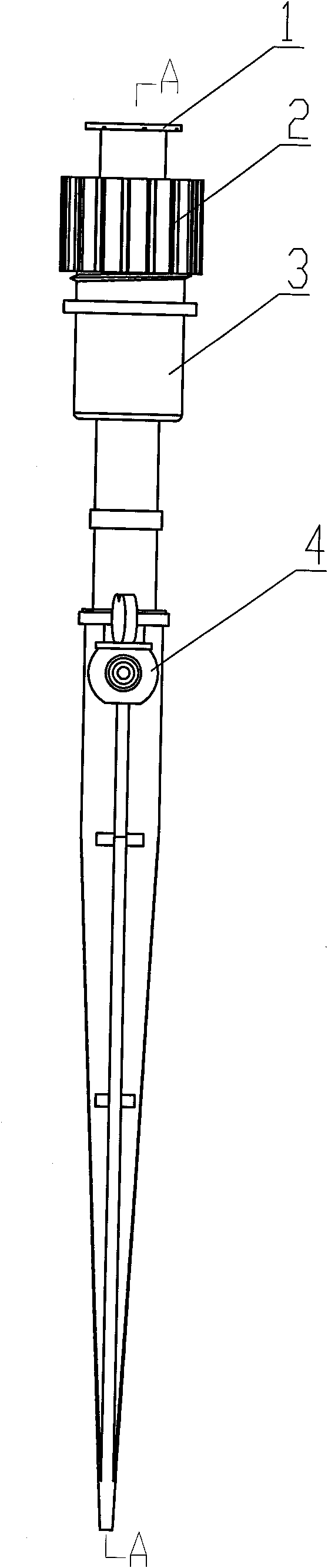
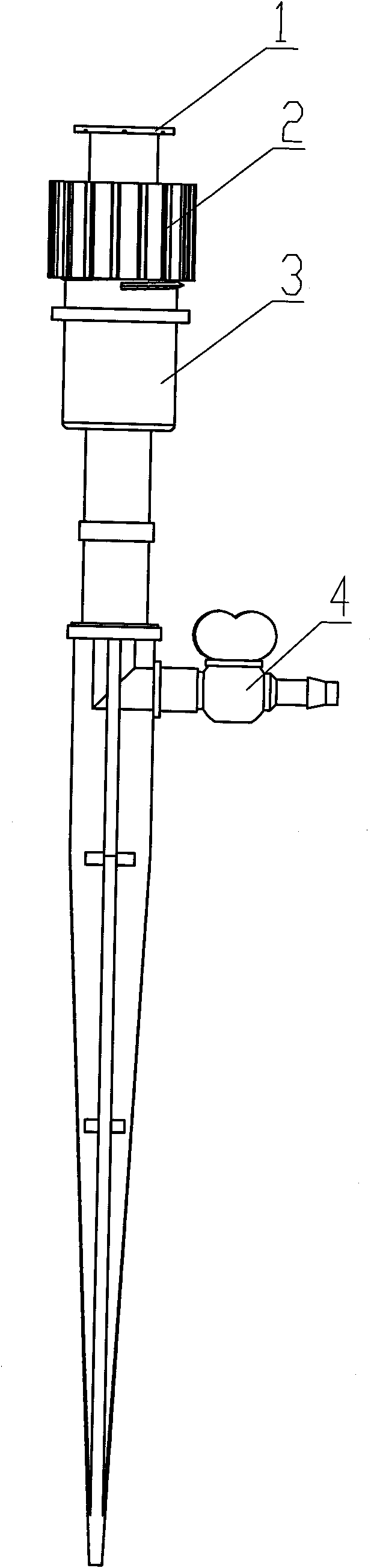
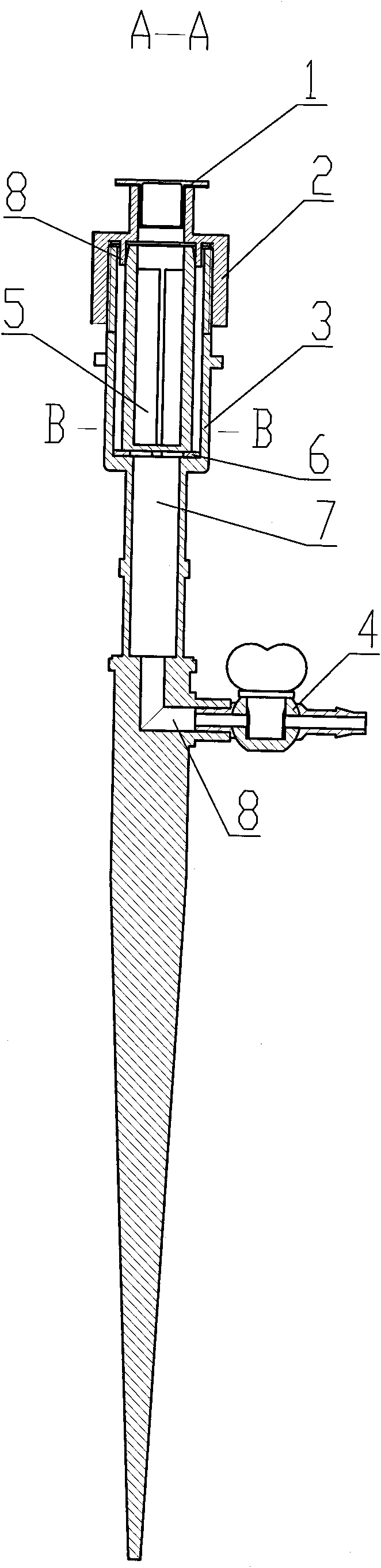
[0016] Such as figure 1 , figure 2 The plunger-type self-filtering adjustable irrigator shown includes a plunger and a spray head arranged on the top of the plunger. The key improvement is that the upper part of the plunger 3 is provided with a flow channel 7 along its central axis, and the top of the flow channel 7 The gland 2 is connected to the nozzle 1, and a water inlet 8 for connecting to the valve 4 is provided corresponding to the bottom end of the flow channel. The axis of the water inlet 8 is perpendicular to the central axis of the plunger 3, and a valve 4 is provided on the water inlet. The function of the valve 4 is to adjust the flow rate. , The flow channel 7 is provided with a filter element 5; the lower cross section of the plunger is cross-shaped, the upper part is cylindrical, or the lower part is conical, the upper part is cylindrical, and there is a flow channel along the axis of the cylindrical part, and the flow channel 7 is from the bottom The upper part has a gradually increasing stepped structure, and the filter element 5 is arranged on the upper part of the flow channel.
[0017] Such as image 3 , Image 6 Shown: The filter element 5 is a cylindrical structure with one end closed, including a frame 5-1 and a filter screen 5-2 plastic-mounted on the frame as a side wall. The inner diameter of the channel, and there is a certain uniform gap with the inner wall of the flow channel 7, the bottom closed surface of the filter element 5 is set on the step formed between the uppermost section of the flow channel 7 and the second section from top to bottom. On the evenly distributed radial boss 6, the top of the filter element is sleeved in the annular positioning sleeve 9 set at the lower part of the gland 2, dividing the flow channel 7 into two parts. The water flowing into the flow channel 7 must be filtered by the filter element 5 before it can flow to the nozzle 1. Effectively prevent the nozzle clogging from affecting the efficiency of the irrigator.
[0018] Such as image 3 , Figure 4 , Figure 5 Shown: The top of the plunger 3 is provided with a gland 2 threaded to it, and the top of the gland 2 is fixedly connected to the nozzle 1. The nozzle 1 and the gland 2 can be clamped or connected by threads, and can be irrigated according to different crops Different types of sprinklers can be selected for different needs.
[0019] Such as Figure 4 , Figure 5 The gland 2 shown is a hollow stepped slewing body with a large lower part and a small upper part. The lower hollow part is provided with internal threads to cooperate with the external threads at the top of the plunger 3, and the top surface of the lower hollow part is along the rotation axis of the gland 2 A downwardly protruding annular positioning sleeve 9 with an inner diameter corresponding to the outer diameter of the filter element 5 is provided, and the top end of the upper hollow part of the gland 2 is fixedly connected with the nozzle 1.
[0020] In the specific application process, the plunger-type self-filtering adjustable irrigator is first inserted in a predetermined position, and the water supply branch pipe is connected to the valve 4. At the same time, the opening degree of the valve 4 is determined according to the requirements of the irrigation volume, because the present invention involves The plunger-type self-filtering adjustable irrigator can be used alone or as a micro-irrigation system. Therefore, the water supply valve can be opened for irrigation after the overall micro-irrigation system is established. After the irrigation is completed, valve 4 can be closed. After the connecting end of the plunger is loosened, the plunger and the nozzle 1 and gland 2 installed on the plunger can be retracted, which effectively improves the service life of the plunger-type self-filtering adjustable irrigator and prevents the irrigator from being stolen. Bring economic losses.

PUM

no PUM

Description & Claims & Application Information

We can also present the details of the Description, Claims and Application information to help users get a comprehensive understanding of the technical details of the patent, such as background art, summary of invention, brief description of drawings, description of embodiments, and other original content. On the other hand, users can also determine the specific scope of protection of the technology through the list of claims; as well as understand the changes in the life cycle of the technology with the presentation of the patent timeline. Login to view more.

Similar technology patents

Auxiliary operation device of computer

InactiveCN108041815Aprevent theftGood security protection
Owner:企客科技(广州)有限公司

Door lock device for vehicle

InactiveUS20150167360A1prevent theft
Owner:HYUNDAI MOTOR CO LTD

Classification and recommendation of technical efficacy words

  • avoid clogging
  • prevent theft

Biologic filtration method and device for purifying industrial organic waste gas

InactiveCN101708426Aavoid cloggingstable airflow
Owner:GUANGDONG INST OF MICROORGANISM

Reversible short lane signal control method based on intersection vehicle in-turn release

InactiveCN104504915Aavoid cloggingIncrease the number of import lanes
Owner:JIANGSU UNIV

Table tennis ball serving device for sports training

ActiveCN108992901Aavoid clogging
Owner:平邑县经发园区运营管理有限公司

Dispensing system

ActiveUS20070278164A1easily manufactureprevent theft
Owner:WESTROCK SHARED SERVICES LLC

Lug nut locking device

Owner:GUMMERT RANDY A

Anti-Theft Location Check Device

ActiveUS20090009283A1prevent theft
Owner:ARBOPROFIT
Why Eureka
Try Eureka