Supercharge Your Innovation With Domain-Expert AI Agents!

Resource allocation method, device and system

A resource allocation device and resource allocation technology, applied in the field of resource allocation methods, devices and systems, can solve problems such as inability to allocate resources to relay stations and macro base stations

Active Publication Date: 2013-05-22
DATANG MOBILE COMM EQUIP CO LTD
View PDF0 Cites 0 Cited by
  • Summary
  • Abstract
  • Description
  • Claims
  • Application Information

AI Technical Summary

Problems solved by technology

[0006] However, in the current system including the relay station, it is still impossible to allocate resources for the relay station and the macro base station on the Access link

Method used


Image

  • Resource allocation method, device and system
  • Resource allocation method, device and system
  • Resource allocation method, device and system

Examples


Embodiment Construction

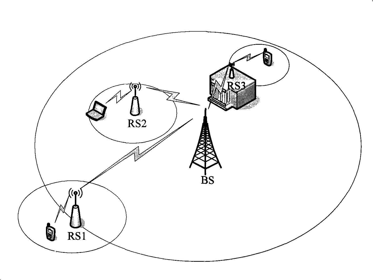
[0025] Embodiments of the present invention provide a resource allocation method, device and system, which are used to allocate Access link resources for relay stations and macro base stations in a system including relay stations.

[0026] On the Access link, in order to improve resource occupancy efficiency, the user equipment of the relay station and the user equipment of the eNB send / receive data at the same time. A reasonable resource allocation method is adopted between devices to achieve the effect of increasing system capacity or system edge coverage.

[0027] The technical solutions provided by the embodiments of the present invention will be described below in conjunction with the accompanying drawings.

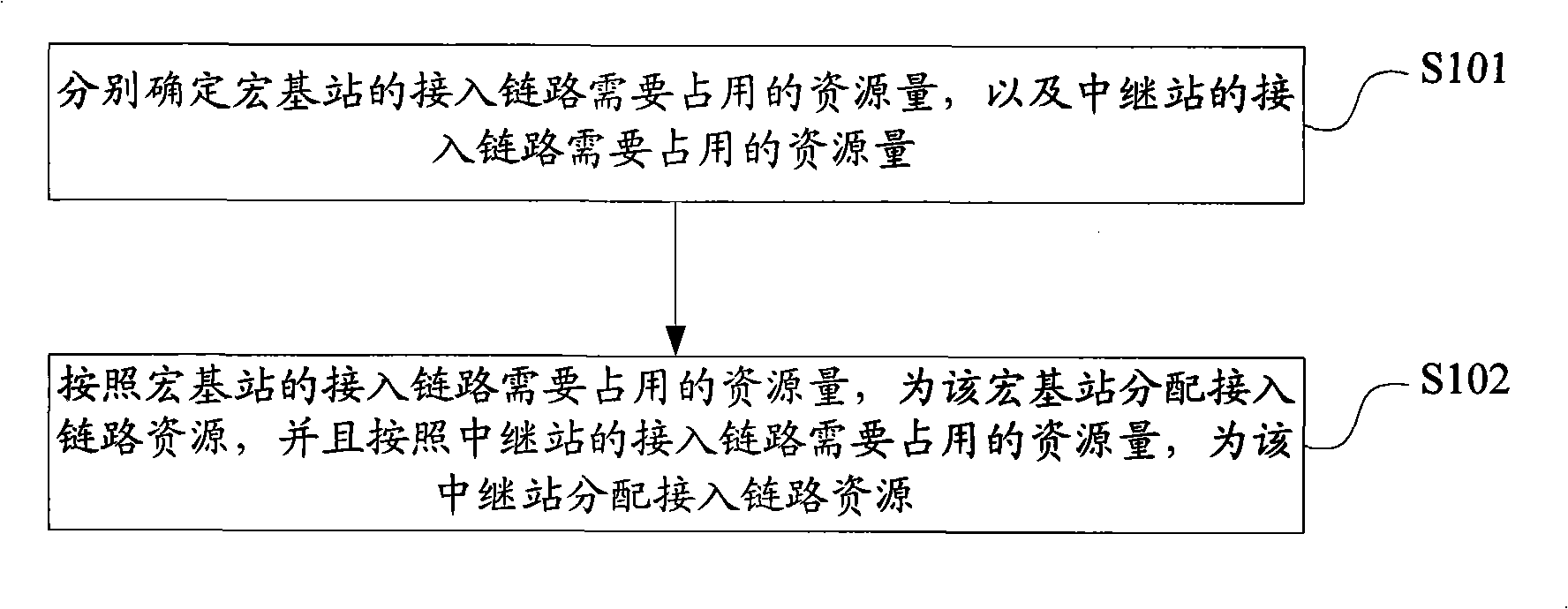
[0028] see figure 2 , a resource allocation method provided by an embodiment of the present invention includes steps:

[0029] S101. Determine the amount of resources required to be occupied by an access link of a macro base station and the amount of resources req...


PUM


Abstract

The invention discloses a resource allocation method and a resource allocation system, which are used for allocating Access link resources for a relay station and a macro base station in a system containing the relay station. The resource allocation method provided by the invention comprises the steps of: determining the resource amount which is needed to be occupied by an access link of the macro base station and the resource amount which is needed to be occupied by an access link of the relay station respectively; and allocating the access link resources for the macro base station accordingto the resource amount which is needed to be occupied by the access link of the macro base station, and allocating the access link resources for the relay station according to the resource amount which is needed to be occupied by the access link of the relay station.

Description

technical field [0001] The present invention relates to the field of communication technologies, and in particular to a resource allocation method, device and system. Background technique [0002] The relay (Relay) technology is an important feature of the Long Term Evolution-Advanced (LTE-A) system, and the introduction of the relay (Relay) technology can improve system capacity or expand system coverage. [0003] see figure 1 , the relay (Relay) technology is to relay the data transmitted between the evolved base station (eNB) and the user equipment (UE) through the relay station (RS, Relay Station), and effectively fill the coverage hole and shadow blind spot caused by insufficient coverage. The UE may be referred to as a user equipment (Relay UE) of a relay station. The UE that directly transmits data with the eNB without RN intermediary may be called a macro user equipment (MacroUE), or a user equipment of the eNB. The eNB may be called a macro base station. figure ...

Claims


Application Information

Patent Timeline
Patent Type & Authority Patents(China)
IPC IPC(8): H04W16/10H04W72/04
Inventor 贾保灵秦飞张杰张利杰
Owner DATANG MOBILE COMM EQUIP CO LTD
Features
  • R&D
  • Intellectual Property
  • Life Sciences
  • Materials
  • Tech Scout
  • Unparalleled Data Quality
  • Higher Quality Content
  • 60% Fewer Hallucinations
Learn More