Three-dimension scanning large gradient electromagnetic guiding device

A three-dimensional scanning, electromagnetic guidance technology, applied in the field of research and development, can solve the problems of non-adjustable magnetic field intensity and gradient, difficult control of frequency and pulse duty cycle, etc. Effect

Inactive Publication Date: 2010-11-17
HUAZHONG UNIV OF SCI & TECH
View PDF9 Cites 5 Cited by
  • Summary
  • Abstract
  • Description
  • Claims
  • Application Information

AI Technical Summary

Problems solved by technology

[0004] At present, the external magnetic field guidance devices in the target area mainly include: ① rare earth permanent magnets and bipolar electromagnets are used, the structure is simple and convenient, and static magnetic fields are provided, but the magnetic field strength and gradient cannot be adjusted; ② permanent magnet pulse magnetic field generators use permanent magnets The relative movement with the target area generates

Method used


Image

  • Three-dimension scanning large gradient electromagnetic guiding device
  • Three-dimension scanning large gradient electromagnetic guiding device
  • Three-dimension scanning large gradient electromagnetic guiding device

Examples


Example Embodiment

[0017] Example one:

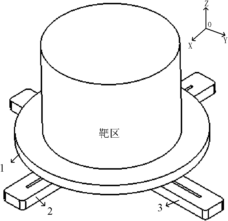
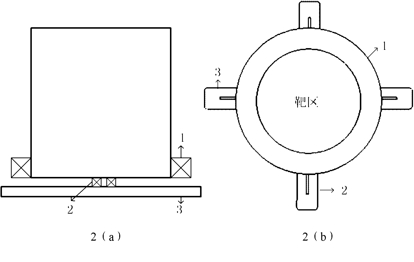
[0018] Such as figure 1 with 2 As shown, the main magnet 1 is a cylindrical coil type magnet with the axial direction in the Z direction. According to the shape of the target zone, different magnets with radial distribution can be designed, such as cylindrical, elliptical, and square cylindrical shapes. This embodiment is designed It is cylindrical, and the purpose of the magnet is to determine the Z coordinate position of the target space.

[0019] Magnets 2 and 3 that make up the scanning magnet are flat rectangular coil magnets. They are placed on double-layer guide rails. Their long sides are perpendicular to the guide rails. There is a fixed sliding device at the connection. The driving device drives them to scan back and forth in the XY plane. The magnet axis is the Z direction. The purpose of the scanning magnet is to superimpose a gradient magnetic field on the basis of the background field to determine the particle concentration position in the XY pl...

Example Embodiment

[0021] Embodiment two:

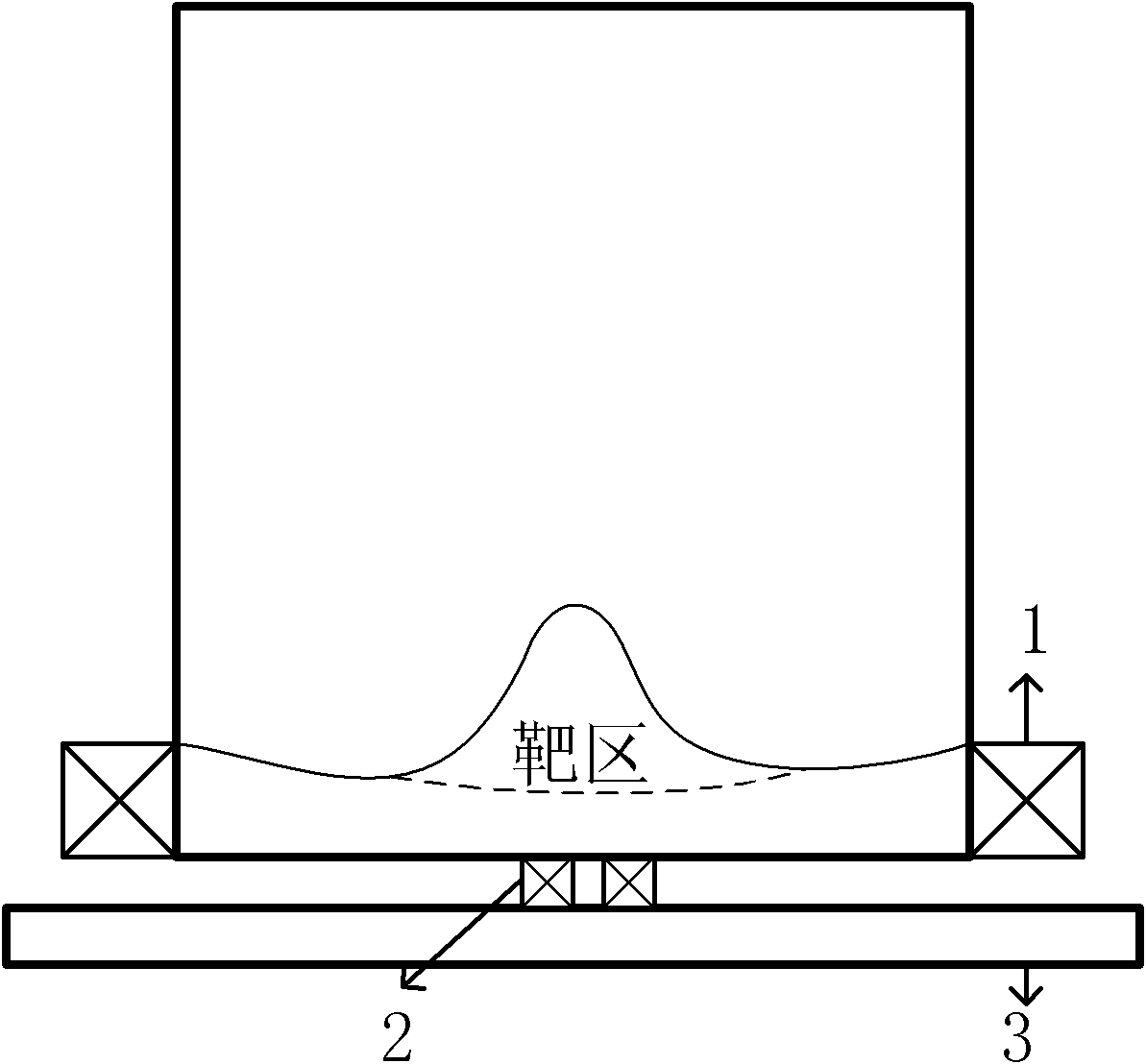
[0022] Such as Figure 4 As shown, the difference between this example and the first embodiment lies in the composition of the scanning magnet. In this example, the scanning magnet adopts a cylindrical coil magnet 4 (not limited to the cylindrical shape, the cross-sectional shape can be arbitrarily selected), and the magnet axis is Z direction. The magnet superimposes a point gradient magnetic field on the background field generated by the main magnet, and determines the particle concentration position in the XY plane of the target area. A more concentrated area of ​​magnetic force is generated near the cylindrical magnet 4, and the position of this area can be changed by controlling the movement of the magnet 4.

[0023] Figure 5 Shown is a schematic diagram of an application example of the present invention. Put a vessel containing small magnetic drug molecules into the device of the present invention. According to the characteristics of electromagneti...


PUM


Abstract

The invention discloses a three-dimension scanning large gradient electromagnetic guiding device, which uses a superposition principle of a gradient field in space to generate a planar ambient field at target region by a main magnet; according to guiding requirements of the target region, scanning magnets with different structures can be selected in a combined mode to produce planar, linear and pointed gradient fields in the target region. By controlling the different scanning modes of the magnets in the target region, a scanning dynamic area gradient field is formed to guide magnetic particulates to carry out more refined movement at the target region. For a drug screening system, the device can strengthen activation efficiency of receptors and improve action effect between the drug and the receptors; and for an in-vitro gene transmission system, the device can provide a flexible and effective transmission guiding mean and improves transmission efficiency.

Description

technical field [0001] The invention relates to an electromagnetic guidance device, which is used for the targeted guidance of magnetic particles, and is especially suitable for the research and development fields of biology and medicine, which can improve the level of drug screening and drug efficacy evaluation, and enhance drug / gene transport and therapeutic effect. Background technique [0002] Drug targeting technology is a research hotspot and cutting-edge technology in the fields of modern biology and medicine such as tumor chemotherapy, radiotherapy and gene therapy. Among many targeted therapy systems, the electromagnetic guidance system of magnetic particles shows obvious advantages. It combines drugs, magnetic substances and appropriate carrier materials. And released, with the characteristics of high efficiency and low toxicity, it is an important means to carry out targeted drug and gene therapy research. [0003] The basic technical problems that need to be sol...

Claims


Application Information

Patent Timeline
IPC IPC(8): A61M37/00
Inventor 韩小涛李亮曹全梁
Owner HUAZHONG UNIV OF SCI & TECH
Why Eureka
Try Eureka