Unlock instant, AI-driven research and patent intelligence for your innovation.

Backlight unit and liquid crystal display device

A backlight unit and light-emitting element technology, applied in the direction of optical elements, lighting devices, cooling/heating devices of lighting devices, etc., can solve the problems of deformation of the mounting substrate 111, insufficient heat dissipation of the heat sink, etc., and achieve the effect of reliable emission

Inactive Publication Date: 2010-12-29
SHARP KK
View PDF1 Cites 7 Cited by
  • Summary
  • Abstract
  • Description
  • Claims
  • Application Information

AI Technical Summary

Problems solved by technology

[0005] However, after the backlight unit 149 has been used for a long time, it is not enough to dissipate heat only by the heat sink 171 and the heat sink substrate 172, so for example, it is likely to cause deformation of the mounting substrate 111.

Method used


Image

  • Backlight unit and liquid crystal display device
  • Backlight unit and liquid crystal display device
  • Backlight unit and liquid crystal display device

Examples


Embodiment approach 1

[0046] An embodiment will be described below with reference to the drawings. In addition, for the sake of convenience, hatching, reference numerals of components, etc. may be omitted in some cases, and in such a case, please refer to other drawings. In addition, the black dots on the figure indicate the direction perpendicular to the paper surface.

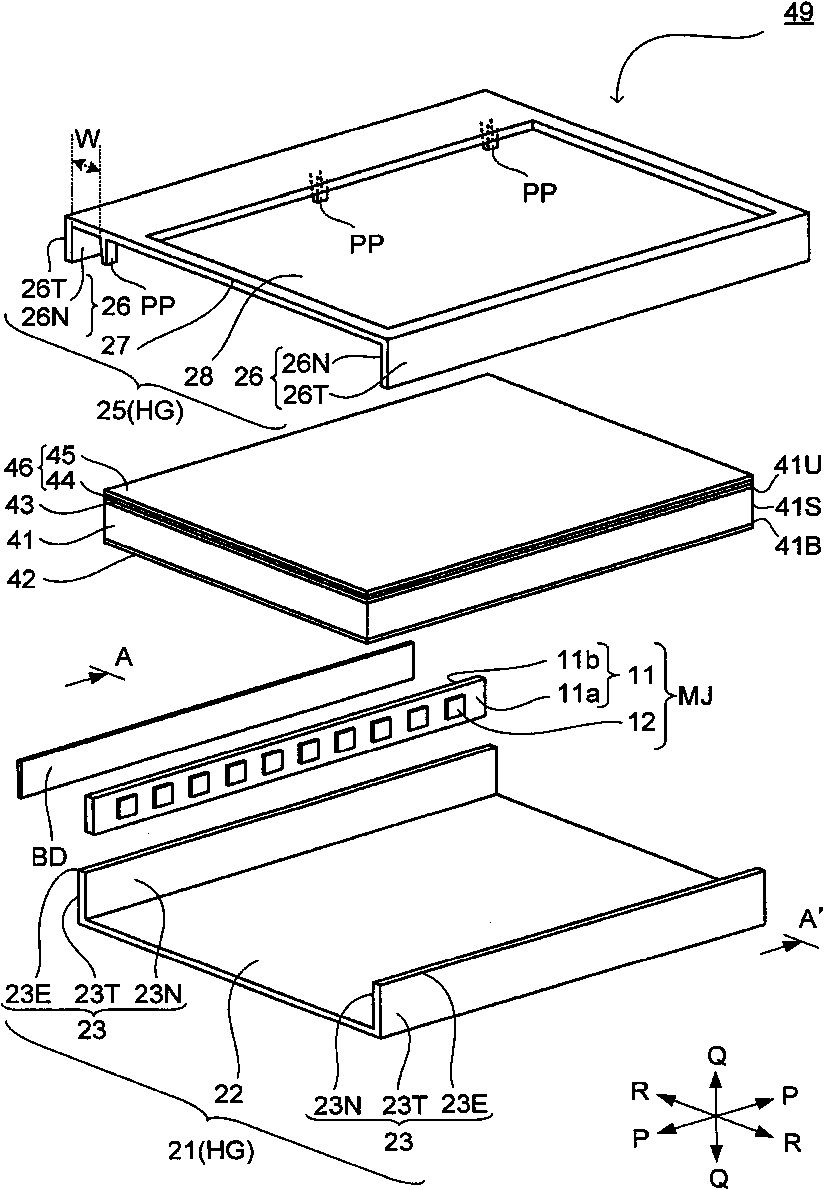
[0047] figure 1 An exploded perspective view showing a backlight unit 49 in a liquid crystal display device, figure 2 is a cross-sectional view of the liquid crystal display device 69 (wherein, figure 2 The direction of the section is figure 1 The cross-sectional direction viewed from the direction indicated by the arrow at the line A-A' in the figure). Such as figure 2 As shown, the liquid crystal display device 69 includes a liquid crystal display panel 59 and a backlight unit 49 .

[0048] In the liquid crystal display panel 59, an active matrix substrate 51 including switching elements such as TFTs (Thin Film Transi...


PUM


Abstract

Disclosed is a backlight unit (49) wherein a flexible pressing piece (PP) provided to a top housing unit (25) presses a mounted substrate (11) against a bottom housing unit (21) which also serves as a heat dissipating unit.

Description

technical field [0001] The present invention relates to a backlight unit having a mounting substrate on which a light emitting element is mounted, and a liquid crystal display device including the backlight unit. Background technique [0002] Conventionally, various backlight units for supplying light to a liquid crystal display panel (non-emissive display panel) of a liquid crystal display device have been developed. Generally, a backlight unit includes a light source that emits light. For example, if Figure 7 As shown in the cross-sectional view of , the backlight unit 149 disclosed in Patent Document 1 uses an LED (Light Emitting Diode: Light Emitting Diode) 112 mounted on a mounting substrate 111 as a light source. In addition, the LED 112 makes light enter the light guide plate 141 , and the light propagates toward the liquid crystal display panel 159 through the light guide plate 141 , the reflection sheet 142 , and the optical sheet group 146 . [0003] This light ...

Claims


Application Information

Patent Timeline
Patent Type & Authority Applications(China)
IPC IPC(8): F21S2/00F21V29/00G02F1/13357F21Y101/02
CPCG02B6/0088G02B6/0068G02F2001/133628G02B6/0073G02B6/0085G02F1/133615G02F1/133628
Inventor 滨田哲也
Owner SHARP KK