Supercharge Your Innovation With Domain-Expert AI Agents!

Continuous heat-transfer printing system of steel plate belt

A technology of thermal transfer and thermal transfer paper, applied in transfer printing, rotary press, printing, etc., can solve the problems of insecure quality, complex sealing device, poor transfer quality, etc., and achieve easy operation and control. Automation, improving the efficiency of thermal transfer printing, and ensuring the effect of printing quality

Active Publication Date: 2012-07-11
殷灵语
View PDF1 Cites 0 Cited by
  • Summary
  • Abstract
  • Description
  • Claims
  • Application Information

AI Technical Summary

Problems solved by technology

Such thermal transfer equipment has at least the following disadvantages: ①The thermal transfer operation is discontinuous, requiring manual operation, opening and closing the frame back and forth, the process is cumbersome, the quality is not guaranteed, and the efficiency is extremely low; ②The thermal transfer equipment The normal use of the machine needs to add a sealing device at the opening and closing ends of the upper and lower racks, and the transfer bed is generally large, and the upper and lower racks are frequently opened and closed, the sealing device is very complicated, the sealing effect is poor, and it is easy to run out of air and transfer. Poor print quality
[0003] For this reason, Chinese patent 200720127283.1 discloses a nested vacuum transfer bed. Although some improvements have been made to the above-mentioned technical solution, it still adopts a non-continuous operation mode and still fails to solve the cumbersome process of traditional thermal transfer technology. Quality is not guaranteed, technical problems with extremely low efficiency

Method used


Image

  • Continuous heat-transfer printing system of steel plate belt
  • Continuous heat-transfer printing system of steel plate belt
  • Continuous heat-transfer printing system of steel plate belt

Examples


Embodiment Construction

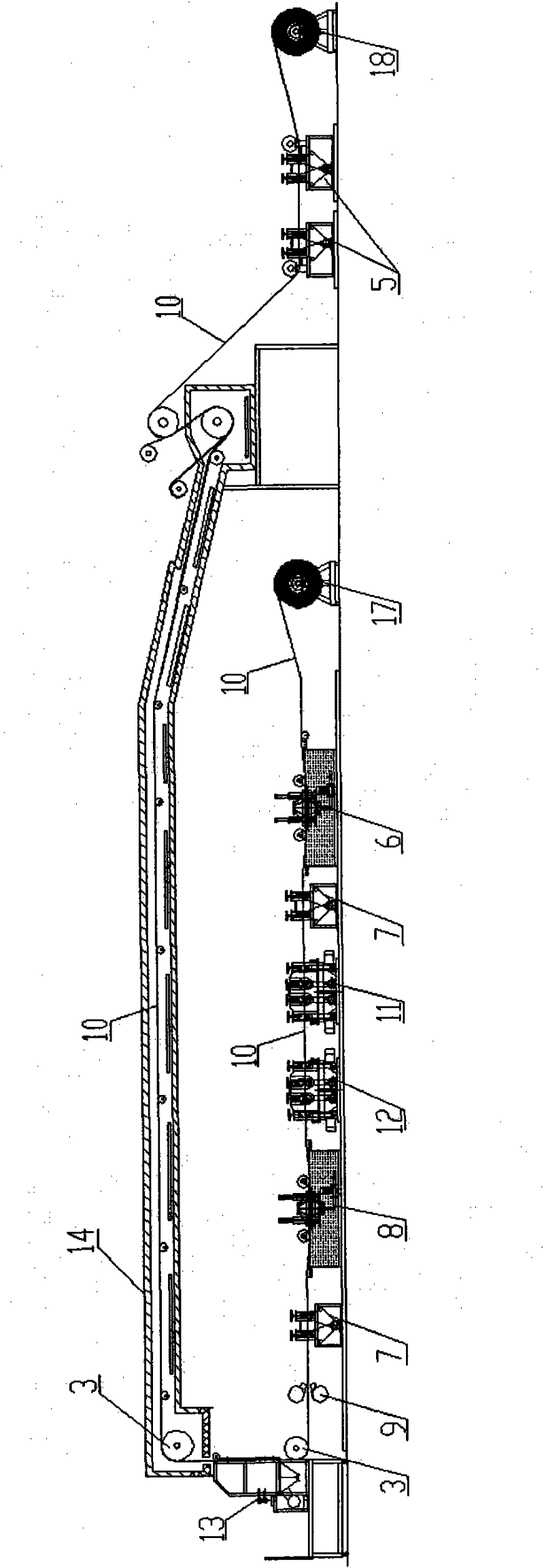
[0024] See attached figure 1 In the structure of a specific embodiment of the present invention, an unwinding machine 17, a cleaning machine 6, a water rolling machine 7, a degreasing machine 11, a texturing machine 12, a rinsing machine 8, a water rolling machine 7, a drying machine 9, a spray Powder machine 13, heating tunnel 14, continuous heat transfer printing equipment for roller-type steel plates and strips, pulling machine 5 and winder 18; two guide rollers 3 are vertically arranged between the drying machine 9 and the heating tunnel 14 , the steel plate strip 10 runs vertically between the two guide roller shafts 3, and turns back and travels horizontally at the upper guide roller shaft 3, and enters the heating tunnel 14; 11 and the top of the texturing machine 12; the powder spraying machine 13 is arranged between the two guide rollers 3;

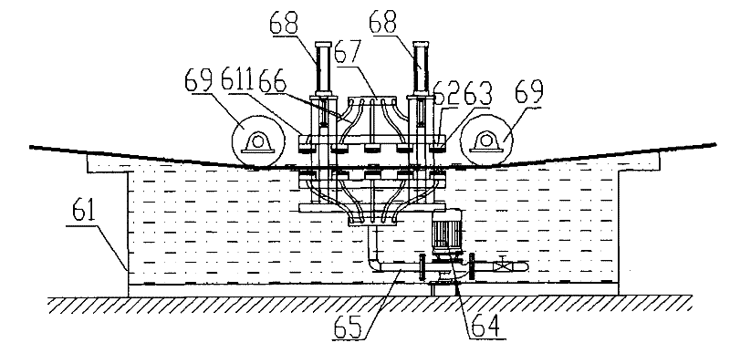
[0025] See attached Image 6 , the unwinding machine 17 includes a support 171, a mandrel 172 and a magnetic powder brake 174...


PUM


Abstract

The invention discloses a continuous heat-transfer printing system of a steel plate belt, which sequentially comprises an unreeling machine, a degreasing machine, a texturing machine, a powder spraying machine, a heating tunnel, roll-shaft type steel-plate-belt continuous heat-transfer printing equipment, a traction machine and a reeling machine, wherein the roll-shaft type steel-plate-belt continuous heat-transfer printing equipment comprises a hot box, a heat-transfer printing roll shaft arranged in the hot box and a receiving and releasing device of heat-transfer printing paper; a lead-in roll shaft and a lead-out roll shaft of the steel plate belt are respectively arranged at both sides of the heat-transfer printing roll shaft, and the axial centers of the lead-in roll shaft, the heat-transfer printing roll shaft and the lead-out roll shaft are in V-shaped distribution; the receiving and releasing device of the heat-transfer printing paper comprises a paper releasing shaft and a paper receiving shaft, which are arranged outside the hot box, and the paper releasing shaft and the paper receiving shaft are positioned between the lead-in roll shaft and the lead-out roll shaft; thelead-in roll shaft of the steel plate belt is positioned inside the hot box, and the lead-out roll shaft is positioned outside the hot box; and a heater is arranged in the hot box. The invention can continuously operate to carry out heat-transfer printing on the steel plate belt, the transfer printing effect is easy to control, and the transfer printing efficiency is greatly improved.

Description

technical field [0001] The invention relates to a steel plate strip printing equipment, in particular to a roller-type steel plate strip continuous thermal transfer equipment system. Background technique [0002] At present, in order to beautify the steel plate, patterns are usually transferred on the surface of the plate by heat transfer printing. The method is to place the plate in a vacuum transfer bed, cover the surface of the plate with patterned transfer paper, and start the vacuum pump. Pump air, let the silicone skin of the transfer bed tightly press the outside of the transfer paper, make the transfer paper close to the surface of the board, then push the transfer bed into the oven and heat at 180°C-200°C After 3-5 minutes, the pattern on the transfer paper will be transferred to the surface of the board. Such thermal transfer equipment has at least the following disadvantages: ①The thermal transfer operation is discontinuous, requiring manual operation, opening an...

Claims


Application Information

Patent Timeline
Patent Type & Authority Patents(China)
IPC IPC(8): B41F16/00
Inventor 马峰然
Owner 殷灵语
Features
  • R&D
  • Intellectual Property
  • Life Sciences
  • Materials
  • Tech Scout
  • Unparalleled Data Quality
  • Higher Quality Content
  • 60% Fewer Hallucinations
Learn More