Elevator device and cable special for elevator

A technology for elevators and cables, which is applied in the direction of textile cables, elevators in buildings, transportation and packaging, etc. It can solve the problems of reducing fatigue life and increasing the bending stress of main cables, so as to achieve the effect of improving life and reducing manufacturing costs

Inactive Publication Date: 2011-04-06
TOSHIBA ELEVATOR KK
View PDF6 Cites 12 Cited by
  • Summary
  • Abstract
  • Description
  • Claims
  • Application Information

AI Technical Summary

Problems solved by technology

For miniaturization, it is important to miniaturize the hoisting machine (not shown) and the pulleys 5a, 5b comprising the drive sheave 3, but due to the miniaturization of the drive sheave 3 and the pulleys 5a, 5b, the generation of the main cable 4 will

Method used


Image

  • Elevator device and cable special for elevator
  • Elevator device and cable special for elevator
  • Elevator device and cable special for elevator

Examples


Example Embodiment

[0039] Hereinafter, an embodiment of an elevator apparatus using the resin-coated cable according to the present invention for the main cable will be described with reference to the drawings.

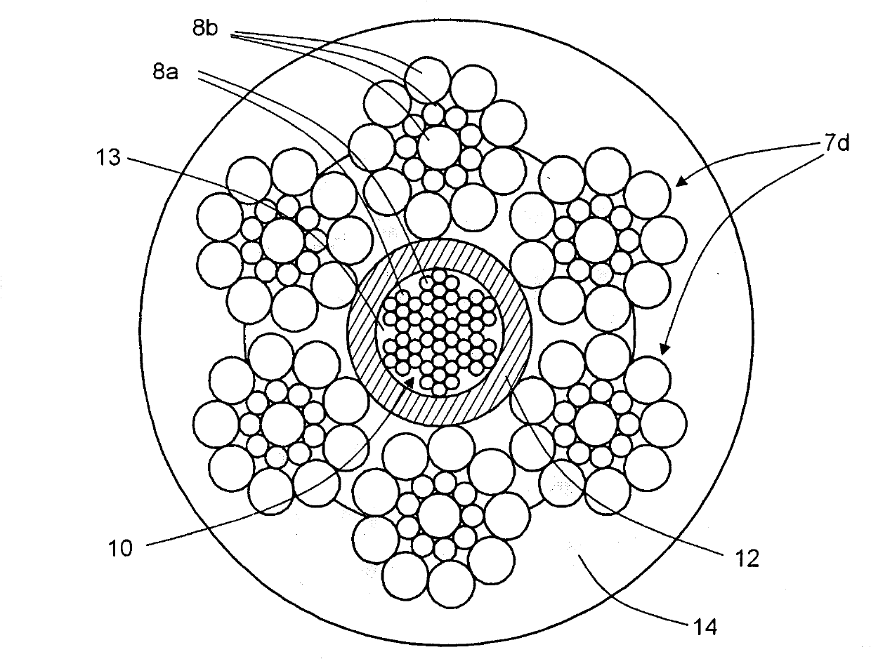
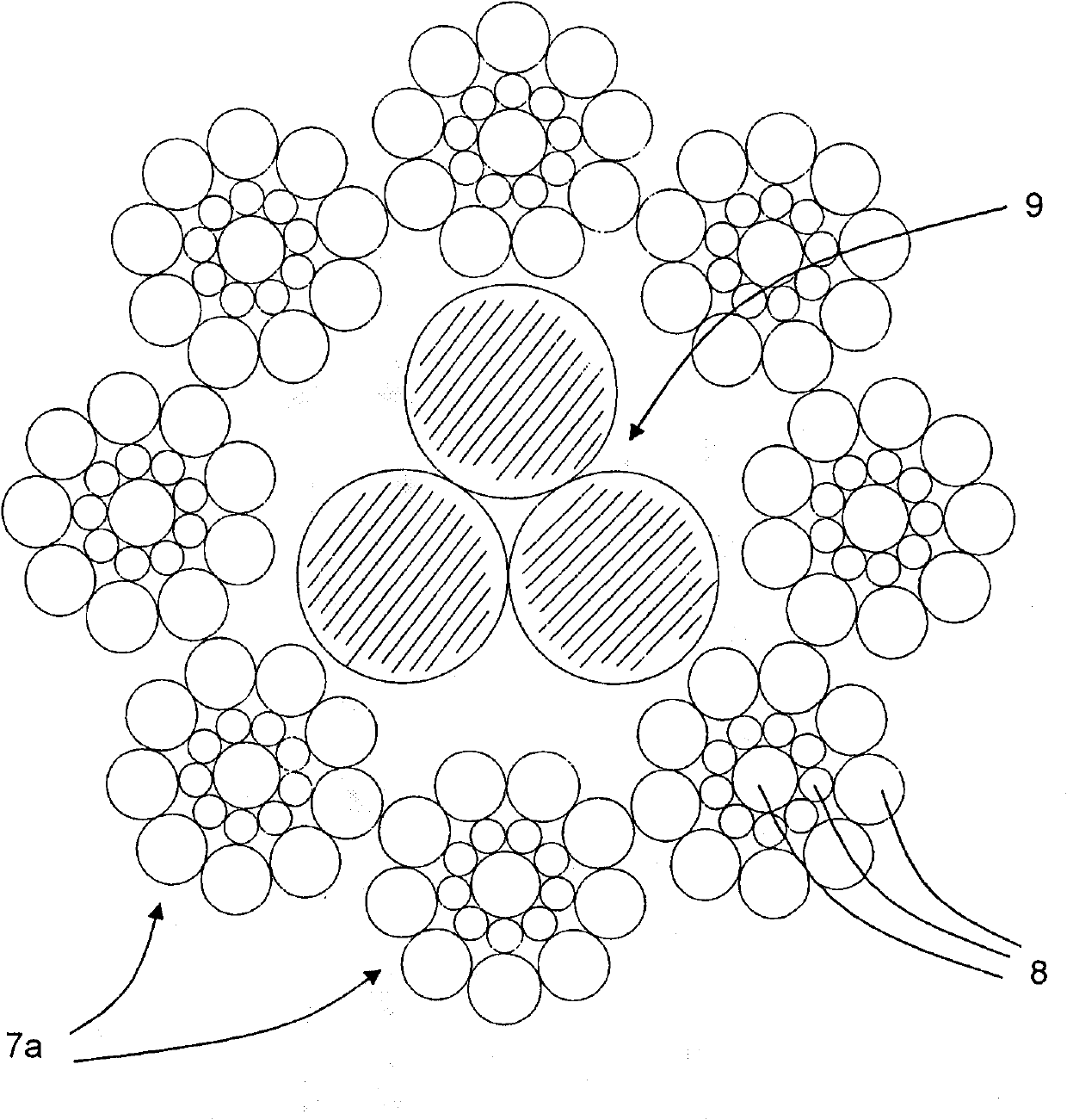
[0040] figure 1 An example of the main rope in the elevator apparatus of the present invention is shown. in figure 1 Here, the steel core 10 is formed by twisting a plurality of steel wires 8a. The braid 12 is configured to braid synthetic fibers into a cylindrical shape and cover the outer circumference of the steel core 10. The strand 7d is formed by twisting multiple steel wires 8b, multiple (such as figure 1 The example shown is 6) strands 7d are arranged to surround the outer side of the core wire covering material 12. An outer covering layer 14 made of polyurethane resin covering the entire outer circumference of the plurality of strands 7d to cover the surface of the cable is formed. The core wire covering material 12 is filled with a solid lubricant 13.

[0041] The core wir...


PUM

PropertyMeasurementUnit
Areaaaaaaaaaaa
Strengthaaaaaaaaaa
Thicknessaaaaaaaaaa

Abstract

The object of the invention is to increase the life of a cable special for an elevator and reduce the manufacture cost. The cable for elevator wholly has an approximately round cross section and comprises: a steel core (10) formed by twisting a plurality of steel lines (8); a core steel cladding material (12) for cladding the synthetic fiber weaved into the cylindrical shape on the whole perimeter of the steel core (10); a solid lubricant (13) filled into the core steel cladding material (12); a plurality of strands (7d) formed by twisting a plurality of steel lines (8) and enclosing the core steel cladding material; and an outer side cladding layer (14) for cladding the whole perimeter of the strands (7d) and the surface of the cable and made by a synthetic resin.

Description

technical field [0001] The present invention relates to elevator installations and elevator ropes. Background technique [0002] In recent years, elevators for low- and middle-rise buildings have generally adopted a structure without a machine room that allows a large degree of freedom in architectural design and can save space. [0003] figure 2 An example of a bucket elevator without a machine room structure is shown. exist figure 2 Among them, 1 is the car, 2 is the balance weight, 3 is the driving sheave set on the winch, 4 is the main cable, 5a and 5b represent the pulleys for lifting the car 1 and the balance weight 2, and 6 is the lifting passage. One end of the main cable 4 is fixed on the top of the hoistway 6, wound in the order of the pulley 5a of the car 1, the drive sheave 3, and the pulley 5b of the counterweight 2, and the other end is fixed on the top of the hoistway 6 again. The difference between the tension on the side of the car 1 of the main cable 4 ...

Claims


Application Information

Patent Timeline
IPC IPC(8): D07B1/16B66B9/00B66B11/00
CPCD07B2205/507D07B2201/2061D07B1/162D07B2201/2062D07B1/144D07B2201/2074D07B2201/2044D07B2501/2007
Inventor 长田朗清水麻衣
Owner TOSHIBA ELEVATOR KK
Why Eureka
Try Eureka