Solar air heat collecting sludge and excrement fermenting and drying system
A technology of solar heat collection and air heat collection, which is applied in the field of sludge and feces drying, can solve the problems of high heat loss rate, high equipment cost, and large amount of heat transfer oil, so as to reduce humidity and water content and overcome small processing scale , Improve the effect of heat energy utilization
- Summary
- Abstract
- Description
- Claims
- Application Information
AI Technical Summary
Problems solved by technology
Method used
Image

Examples
Embodiment 1
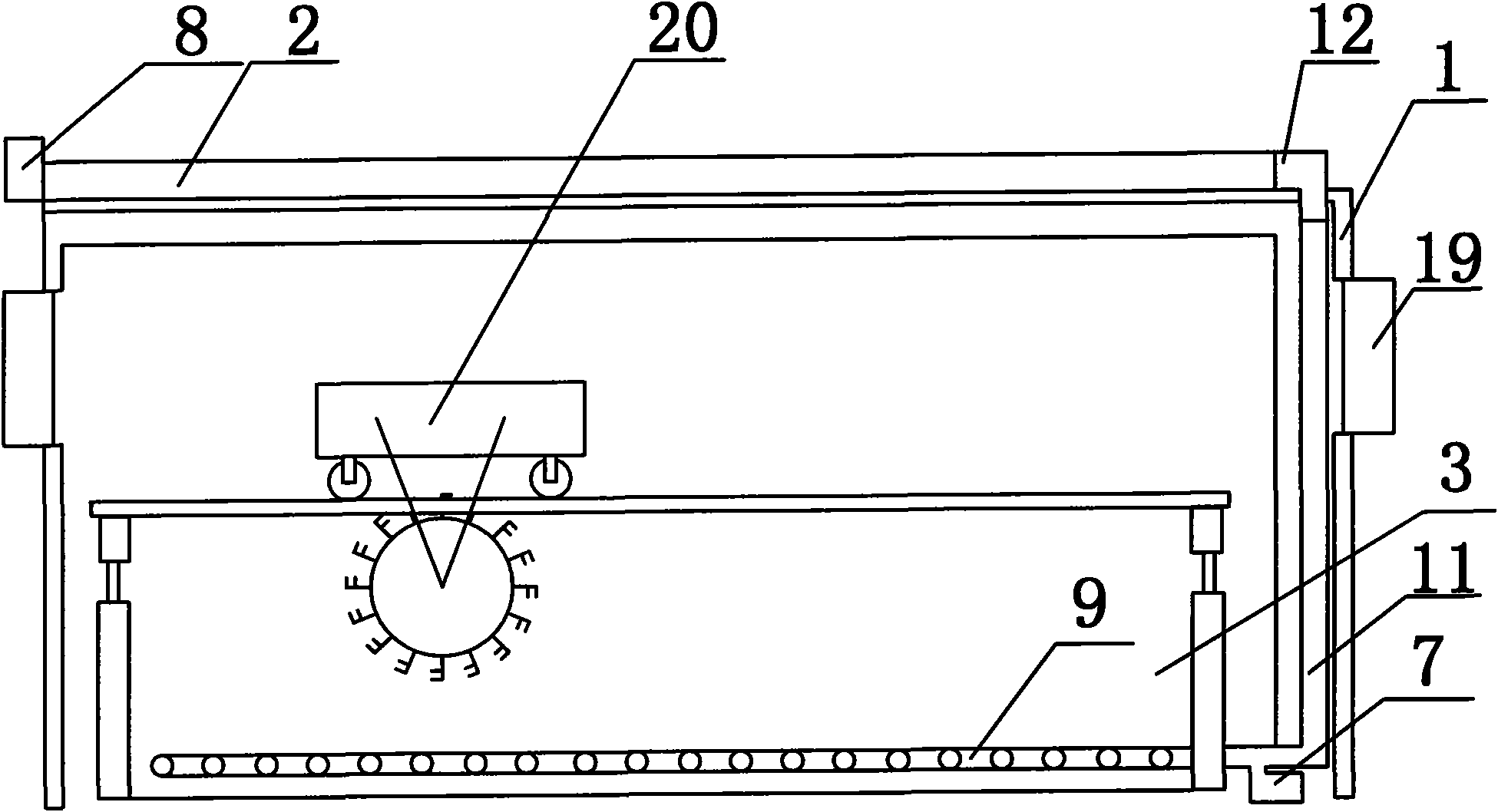
[0032] A kind of solar air heat collection sludge, excrement fermentation and drying system, such as figure 1 As shown, it consists of a thermal insulation shed body 1, a solar heat collection device 2, a sludge pool 3 and a throwing mechanism 20. The sludge pool 3 is arranged at the bottom of the thermal insulation shed body 1, and the solar heat collection device 2 is arranged on the On the upper surface, the turning and throwing mechanism 20 is arranged above the sludge pool 3 in the heat preservation shed body 1, the side wall of the heat preservation shed body 1 is provided with a ventilation fan 19, and the bottom of the sludge pool 3 is provided with a heat storage device 9, and the heat storage device 9 and The solar thermal collectors 2 are connected through an air duct 11, and an induced draft fan 7 is arranged in the air duct 11.
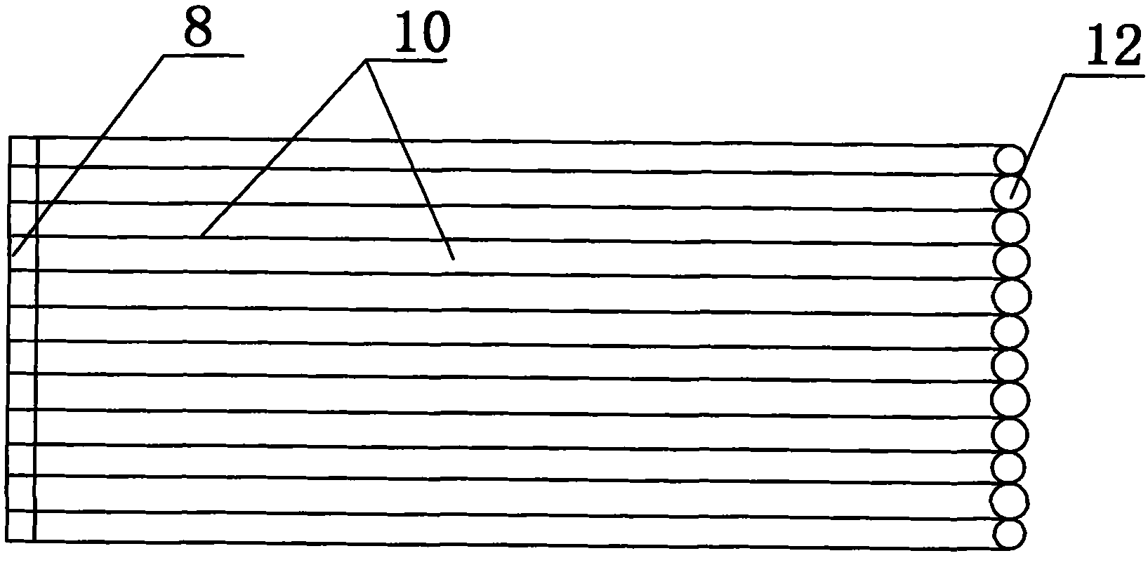
[0033] The solar heat collecting device 2 includes a solar air heat collector 10 and an air collector 12, the air outlet of the solar ai...
Embodiment 2
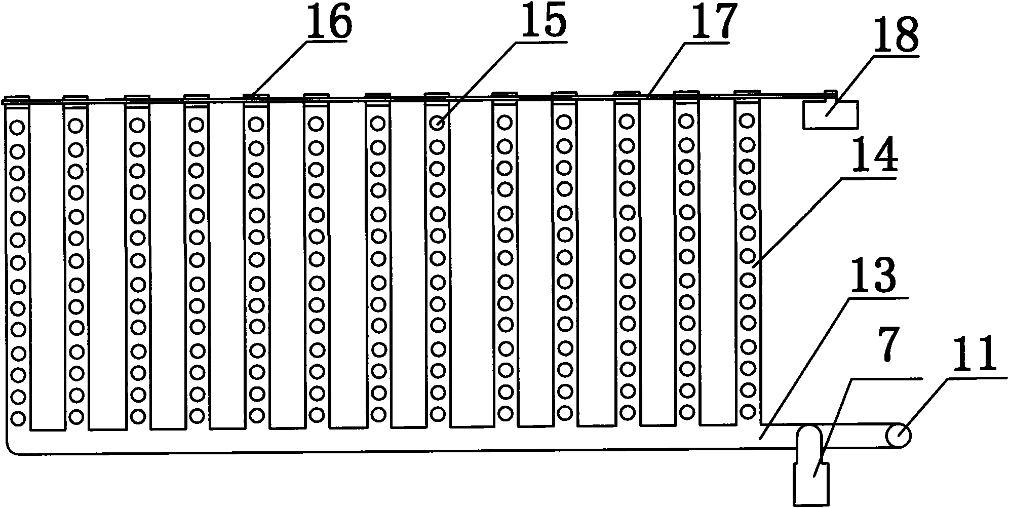
[0037] Solar air heat collection sludge and feces fermentation and drying system as described in Example 1, the difference is that the hot air duct 4 is divided into 20 heat collection air ducts 6 by the air duct partition plate 5, and the distance between the ventilation holes 15 is 0.8cm; the pipe spacing between the sludge drying ventilation pipes 14 is 50cm; the inner diameter of the sludge drying ventilation pipes 14 is 20cm; the power of the geared motor is 5.5kw.
Embodiment 3
[0039] The solar air heat collection sludge and feces fermentation and drying system as described in embodiment 1, the difference is that the hot air duct 4 is divided into 8 heat collection air ducts 6 by the air duct partition plate 5, and the distance between the ventilation holes 15 is 0.5cm; the pipe spacing between the sludge drying ventilation pipes 14 is 40cm; the inner diameter of the sludge drying ventilation pipes 14 is 40cm; the power of the geared motor is 2.2kw.
PUM
| Property | Measurement | Unit |
|---|---|---|
| Aperture | aaaaa | aaaaa |
Abstract
Description
Claims
Application Information
 - Generate Ideas
- Intellectual Property
- Life Sciences
- Materials
- Tech Scout
- Unparalleled Data Quality
- Higher Quality Content
- 60% Fewer Hallucinations
Browse by: Latest US Patents, China's latest patents, Technical Efficacy Thesaurus, Application Domain, Technology Topic, Popular Technical Reports.
© 2025 PatSnap. All rights reserved.Legal|Privacy policy|Modern Slavery Act Transparency Statement|Sitemap|About US| Contact US: help@patsnap.com