Supercharge Your Innovation With Domain-Expert AI Agents!

Cooling structure of electronic equipment

A technology for electronic equipment and cooling structure, which is applied to the structural parts of electrical equipment, cooling/ventilation/heating renovation, electrical components, etc., which can solve the problems of reducing the influence of external environmental factors, failing to obtain heat conduction efficiency, and unable to expect a large scale. , to achieve the effect of miniaturization

Inactive Publication Date: 2011-04-27
HITACHI LTD
View PDF14 Cites 13 Cited by
  • Summary
  • Abstract
  • Description
  • Claims
  • Application Information

AI Technical Summary

Problems solved by technology

[0014] Therefore, in the electronic device structure in which the heat absorbing portion of the heat pipe is connected to the electronic component, and the heat dissipation portion is connected to the inner wall of the housing, when the temperature of the inner wall (radiating portion) of the housing changes due to sunlight, the electronic component ( The temperature of the heat absorbing part) also changes passively, and it cannot be maintained at the specified temperature
[0015] In addition, since the heat pipe adopts a metal tube, the desired heat conduction efficiency cannot be obtained, and the heat energy from the external environment such as solar radiation is transported into the device, which is easily affected by external environmental factors such as solar radiation.
In other words, in the above-mentioned electronic device structure, it cannot be expected to greatly reduce the influence of external environmental factors

Method used


Image

  • Cooling structure of electronic equipment
  • Cooling structure of electronic equipment
  • Cooling structure of electronic equipment

Examples


Embodiment Construction

[0057] Next, embodiments of the present invention will be described with reference to the drawings.

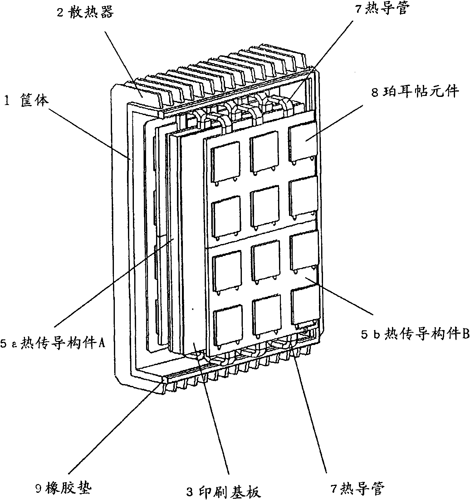
[0058] figure 1 It is a perspective view transparently showing the electronic device of this embodiment.

[0059] This electronic equipment includes: housing 1, radiator 2, printed substrate 3, heat conduction member A5a, heat conduction member B5b, rubber pad 9, heat pipe 7 and Peltier element (heat conduction control member) 8, not shown in the figure Electronic component 4 , control circuit unit 12 , and temperature sensor 13 .

[0060] Figure 6 It is a sectional side view showing the electronic device of this embodiment.

[0061] This electronic device has a housing A1a and a housing B1b, and heat sinks 2 are formed on respective housing surfaces (first surface, second surface) to dissipate heat to the outside atmosphere. The housing A1a and the housing B1b each have sufficient cooling performance and have substantially the same thermal resistance. Moreover, in orde...


PUM


Abstract

In an environment in which influence of heat energy from the outside is received, for example, when a large temperature difference occurs in an electronic equipment by external factors such as solar insolation or when a temperature difference occurs in the electronic equipment by heat of another device installed in the neighborhood, it is difficult to stabilize the temperature of the equipment within an allowable temperature range due to the influence of the external environment. An electronic equipment has a structure in which an electronic component contained in a housing is thermally connected to a housing inner wall through plural heat conduction members and a heat conduction control member, and the amount of heat transported from the electronic component to the housing inner wall is controlled by using the heat conduction control member. The amount of heat to be transported is decreased for a housing surface whose temperature rises by influence of the external environment, the amount of heat to be transported is increased for a housing surface which is not influenced by the external environment, and the temperature of the electronic component is stabilized within the allowable temperature range.

Description

technical field [0001] The present invention relates to the cooling structure of electronic equipment, especially, when the electronic equipment installed outdoors will cause a temperature difference in the electronic equipment due to external factors such as solar radiation or temperature difference in air temperature, as well as other devices installed nearby. The cooling structure of electronic equipment aims at reducing the influence of external heat energy and stabilizing the temperature of the equipment within the allowable temperature range when the heat causes a temperature difference in the electronic equipment. Background technique [0002] In recent years, with the increase in performance and density of electronic equipment, the treatment of heat generated from the equipment has become a major issue. In particular, in precision equipment, the permissible temperature range during operation is often limited, and matters related to heat treatment become strict condit...

Claims


Application Information

Patent Timeline
Patent Type & Authority Applications(China)
IPC IPC(8): H05K7/20G05D23/20
CPCG05D23/192H05K7/20445
Inventor 石仓光男浜岸真也玉山信宏
Owner HITACHI LTD
Features
  • R&D
  • Intellectual Property
  • Life Sciences
  • Materials
  • Tech Scout
  • Unparalleled Data Quality
  • Higher Quality Content
  • 60% Fewer Hallucinations
Learn More